In this third article of a three-part series, the results of selected gas/liquid separation case studies/sensitivities are presented to show the effects of key separator selection/sizing decision parameters, fluid properties, and operational parameters. The results are generated from an Excel spreadsheet model, which incorporates the equations/methods outlined in Part 1 and 2 of this series published in 2013 August and October Oil and Gas Facilities issues, respectively. The Excel Solver add-in is used to find the optimum separator size, in this case defined as the lowest-weight vessel that satisfies the specified separation performance requirements as well as any applicable constraints.
Part 1 of the series in August provided a general discussion of separation equipment classification, as well as existing limitations to methods used for quantifying separator performance. Part 2 in October discussed methods for improved quantification of operating performances of the gas gravity separation, the mist extraction, and the liquid gravity separation sections of gas/liquid separators.
Parts 1 and 2 presented the equations and methods that can be used to improve the quantification of gas/liquid separation performance compared with traditional techniques. The key aspects of the recommended methodology include quantification of the following:
- The amount of gas (liquid) entrained in the form of droplets (bubbles)
- The size distribution of the entrained droplets (bubbles)
- The continuous phase (gas or liquid) velocities
- Droplet (bubble) separation performance based on 1–3 above and the geometry of the separator
The purpose of the articles is to present a more rigorous approach to gas/liquid separator design and rating that more accurately reflects the physics involved. The traditional
Ks/residence-time approach is inadequate for anything but the smallest/simplest separator applications.
The expanding use of computational fluid dynamics (CFD) for separator design purposes has been useful, but does not readily lend itself to the needs of the majority of facilities engineers faced with separator design and operational issues. CFD is expected to be an excellent tool for refining several of the calculations presented in this series of articles. The spreadsheet used to generate the results contained in this article, while complex from a calculational point of view, is quite user friendly.
The spreadsheet will be made available for public use in the near future. To be notified of its availability, please contact the author’s company’s website at www.jmcampbell.com/separatorOGF.
Definition of Base Case Parameters
The main assumptions and parameters used in the Excel spreadsheet to generate the results discussed in this article are as follows:
The fluid properties are assumed as 35°API crude oil; 0.7 SG gas; 100°F operating temperature, and 1,000 psig operating pressure.
Various correlations are incorporated into the spreadsheet to obtain the following fluid properties: gas compressibility factor, gas in solution, dead oil viscosity, live oil viscosity, and liquid surface tension.
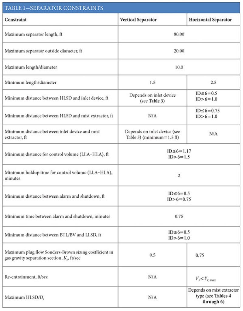
Table 1 shows the constraints of horizontal and vertical separators relevant to the spreadsheet.
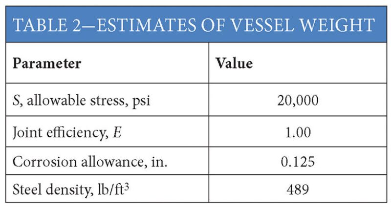
Vessel weight is estimated using the American Society of Mechanical Engineers’ Boiler and Pressure Vessel Code Section VIII equations to calculate shell and head thickness based on the parameters in Table 2.
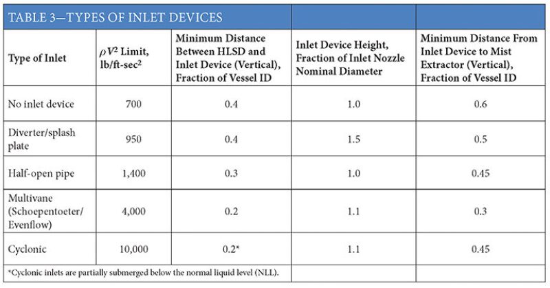
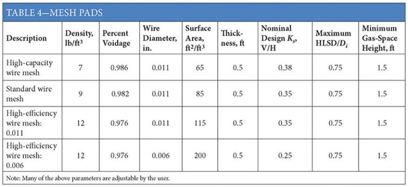
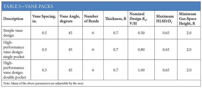
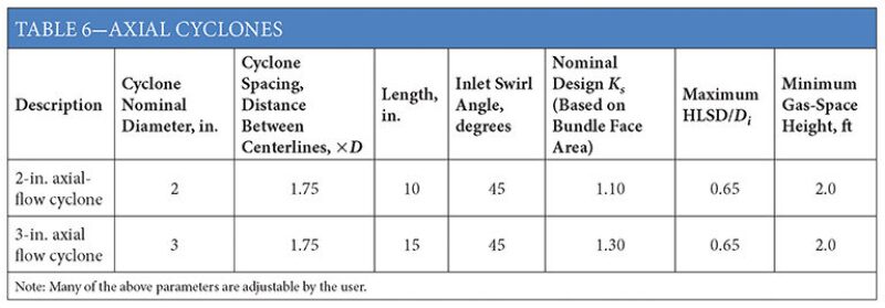
Vessel design pressure is set at 110% of the operating pressure. Nozzle weights, including manway(s) are estimated from a look-up table based on the nozzle size and American National Standards Institute class rating. The weight of the vessel internals is estimated based on the types and sizes of the internals, such as inlet devices (Table 3), mist extractors (Tables 4 through 6), and perforated plates.
Vertical Scrubber Base Case
The following assumptions and parameters define the vertical scrubber base case that will be used as the reference point for the case studies/sensitivities to be discussed in this article.
- Vertical orientation
- 100 MMscf/D, 10 bbl/MMscf
- 1,000 psig, 100°F
- Design factor=1.15
- Slug size=1 second
- Half-pipe inlet device
- Standard mesh pad
- No perforated plates for flow straightening
The separation specifications are allowable liquid of up to 0.1 gal/MMscf in separated gas, and allowable free gas of up to 2% v/v in separated oil. The operational requirements, such as times between alarm and shutdown, are defined by the separator constraints shown in Table 1.
Base Case Results
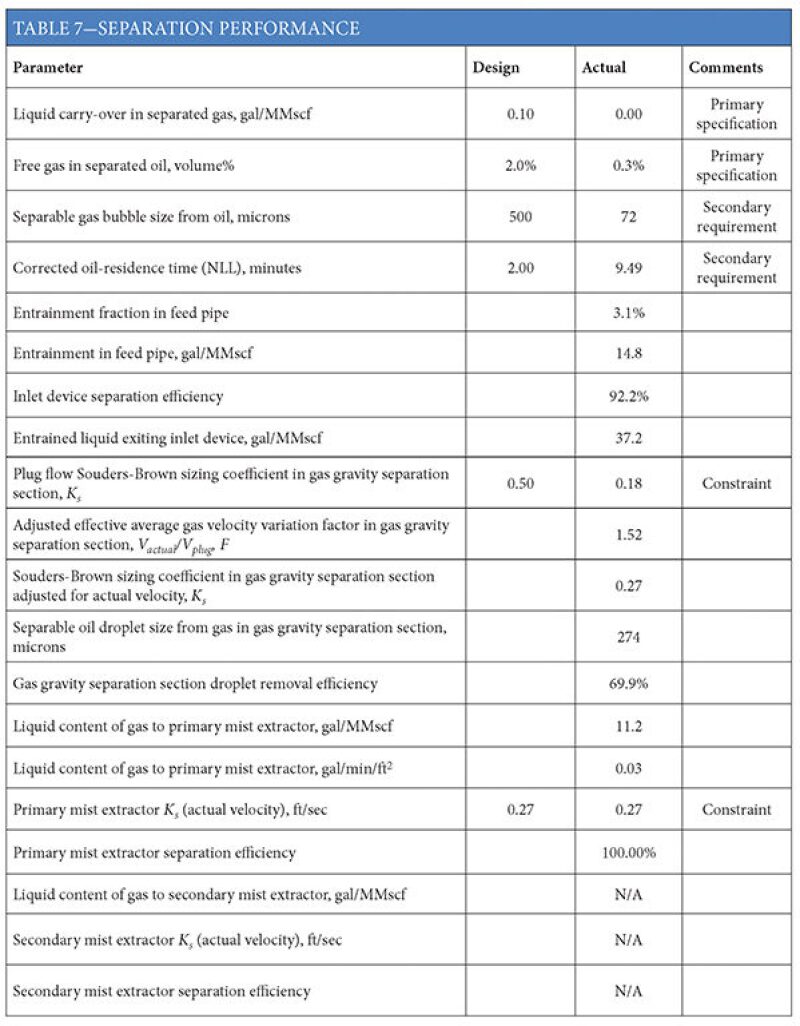
The results are shown in Tables 7 through 11 and Figs. 1 through 4. Droplet size distributions of liquid in gas at different locations are shown in Figs. 1 through 4.


|


|
<


|
The vessel diameter is dominated by gas-handling requirements and is dictated by the type of mist extractor selected, in this case a standard mesh pad. This is typical for low liquid load applications. Vessel diameter is significantly larger than would be calculated assuming uniform plug flow. The estimated degree of gas-flow maldistribution is indicated by the value of F=1.52 in Table 7, the ratio of the actual effective velocity/plug flow velocity (see Fig. 11 in Part 1 of the series). A lower F value, indicating a more uniform flow, could be achieved by using a higher-performance inlet device or a perforated plate, which would reduce the vessel diameter.
As far as liquid handling is concerned, the separator easily achieves the specification of 2.0% free gas in oil, and the liquid levels (alarm and shutdown points) are dictated by the minimum distance constraints. Even the assumed 1-second slug size is accommodated in the control volume (LLA→HLA) using the minimum spacing, although just barely.
The half-pipe inlet has a relatively low rV2 limit, which results in lower feed-pipe velocities, low entrainment (3.1% of feed liquid, 14.8 gal/MMscf), and relatively large liquid droplet sizes.
The Effect of Inlet Liquid Content
Figs. 5 and 6 show the effects of the inlet liquid content while other parameters remain the same as in the base case.
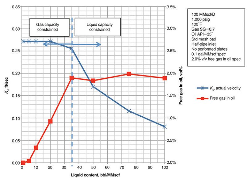
Up to approximately 25 bbl/MMscf inlet liquid, the separator size remains constant. The diameter is dictated by gas-handling capacity via the mist extractor Ks value
(Ks=0.27/ft/sec). As for the base case, the mist extractor area and vessel diameter are larger than would be required, based on the assumption of uniform plug flow.
At more than approximately 25 bbl/MMscf inlet liquid, the separator diameter begins to increase. This is necessary to limit the downward oil velocity to satisfy the specification of 2.0% v/v free gas in oil (Fig. 6).
Note that with respect to degassing performance, residence time is a fairly meaningless criterion for a vertical separator. It is the effective liquid velocity that matters. As the separator diameter increases to handle more liquid, the gas-handling capacity of the separator becomes increasingly underutilized, indicated by the declining value of Ks in Fig. 6. Even with the increasing liquid content over the range shown, the liquid levels are still set by the minimum distance constraints for the liquid level alarm and shutdown points.
A higher-capacity mist extractor (higher Ks) would result in a smaller diameter, lower-weight vessel, but the 2.0% v/v free gas in oil specification would be reached at a lower inlet liquid content, because of the higher downward oil velocities associated with the reduced diameter.
The Effect of the Feed-Pipe Size
Fig. 7 shows the effect of the feed-pipe size while other parameters remain the same as in the base case.
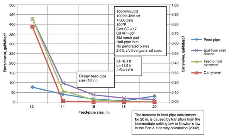
In this case, the separator dimensions are fixed at those obtained for the base case design (ID=6.1 ft, length=11.5 ft). The feed-pipe size is varied to determine the effect on separation performance, or rating calculations.
While the amount of liquid entrained at feed-pipe conditions increases with decreasing feed-pipe size below the design size of 16 in., the amount of entrainment exiting the inlet device and reaching the mist extractor increases much more significantly. This is mainly caused by the increased entrainment, increased droplet shearing, and reduced separation efficiency of the half-pipe inlet device because of excessive ρV2 values associated with the smaller feed-pipe sizes (see Fig. 9 in Part 1 of the series).
The difference in entrainment loads between the “exit from inlet device” and “inlet to mist extractor” curves in Fig. 7 reflects the separation performance of the gas gravity separation section part of the separator.
The amount of free gas in oil was unchanged at 0.3% v/v for all feed-pipe sizes.
The Effect of the Inlet Device
Fig. 8 shows the effect of the inlet device on vertical scrubber weight while other parameters remain the same as in the base case.
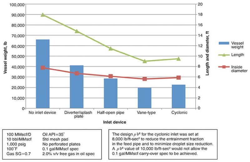
The main effect of inlet device type on diameter relates to gas flow distribution as reflected by the F factor. The selected inlet device also affects vessel length/height via the minimum distance requirements as outlined in Table 3.
Fig. 8 shows a slight increase in vessel size for the cyclonic inlet. Inspection of the spreadsheet calculations shows that if the feed pipe is sized for the limiting ρV2 value of 10,000 lb/ft-sec2 typically specified for a cyclonic inlet, the liquid entrainment fraction in the feed pipe is high, and the entrainment droplet size distribution is shifted to smaller sizes.
Even though the cyclonic inlet is estimated to achieve good liquid-separation efficiency at these conditions, the amount of unseparated liquid and its size distribution overwhelms the mist extractor such that it cannot achieve the 0.1 gal/MMscf specification. Therefore, it is necessary to reduce the design feed-pipe/inlet device rV2 value. In Table 3, it has been assumed that the cyclonic inlet also has a larger inlet device–mist extractor distance requirement than the vane-type inlet.
A standard cyclonic inlet device would not typically be expected to be particularly good with respect to flow distribution. In Part 1, Fig. 11, the curve for the cyclonic inlet device assumes it is equipped with mixers on the fluid outlets to substantially remove spin from the fluids and thereby improve flow distribution. If the cyclonic inlet is not equipped with these outlet mixers, flow distribution can be expected to be poor, and a perforated plate would be necessary to improve flow distribution.
The amount of free gas in oil was <0.4% v/v for all inlet devices.
The Effect of Mist Extractor Type on the Vertical Scrubber
Figs. 9 and 10 show the effects of mist extractor types while other parameters remain the same as in the base case.
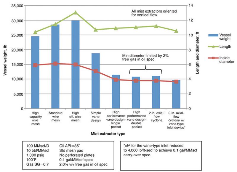
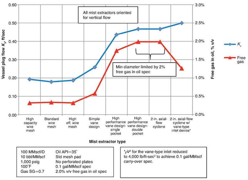
For the low liquid loading base case conditions, vessel diameter is essentially a function of the mist extractor Ks value. The higher-capacity mist extractors allow higher gas velocities and, therefore, smaller diameters for a given gas flow rate.
As can be seen in Fig. 10, the high-performance double pocket vane and 2-in. axial–flow cyclone cases are actually constrained by the 2% free gas in separated oil spec. The 2-in. axial-flow cyclone with vane-type inlet case is constrained by the maximum vessel plug flow Ks value of Ks=0.5 ft/sec limitation (Table 1).
While this may seem to be a conservative assumption that negates the potential capacity advantages of high-performance vane and cyclone demister designs, there is evidence from the field that this conservatism is warranted. This view may change as more data become available and vessel internals are improved further.
In this case, even though the vessel diameter went down slightly, the amount of free gas in the separated oil decreased. This is explained by the better flow distribution of the gas and liquid phases achieved by the vane-type inlet compared to the half-pipe inlet.
The Effect of Liquid Content on Horizontal Separator Sizing
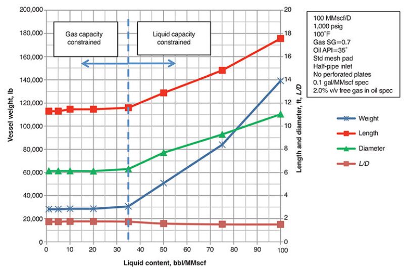
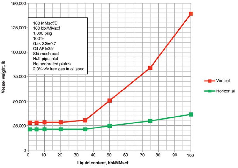
Figs. 11 through 13 show the effect of the liquid content in horizontal separators while other parameters remain the same as in the base case.
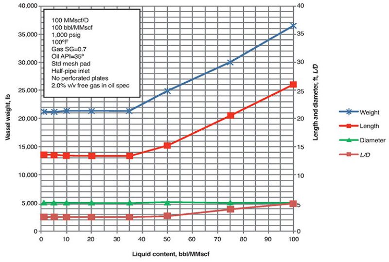
The diameter remains constant at approximately 5.0 ft over the investigated range of inlet liquid content. For these conditions, the diameter is set by two dimensional constraints: 1) the minimum distances between alarm and shutdown levels for the liquid, and 2) the vertical gas-space height required to accommodate the mist extractor and the required minimum space between HLSD and the bottom of the mist extractor. The gas capacity of the gas gravity separation section is acceptably below the Ks=0.75 ft/sec plug flow constraint across the range of inlet liquid contents (Fig. 12).
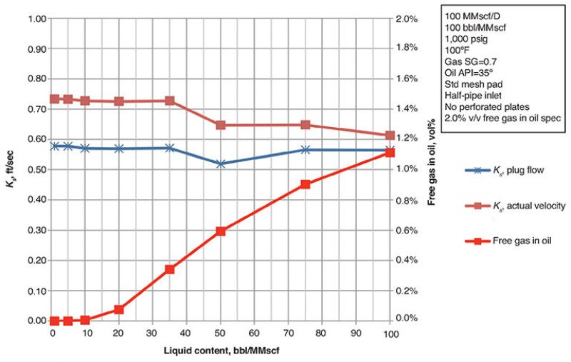
The actual Ks value decreases slowly with increasing inlet liquid content as the separator length increases to accommodate the higher liquid loads. The reason the actual Ks value is decreasing for constant gas flow and constant cross-sectional area of the gas gravity separation section is because of the improvement of the gas velocity profile with increasing L/Di, as shown in Part 1, Fig. 11. Across the range of inlet liquid contents evaluated, the HLSD point is at 53% of the vessel inside diameter. This may seem high for relatively low inlet liquid contents, but is mainly the result of the assumed minimum spacing criteria for liquid level alarm and shutdown points, combined with the high operating pressure that reduces the cross-sectional area required for gas handling.
The constant vessel length of approximately 13.4 ft for low liquid loads is set by the minimum L/D constraint of 2.5. This length is not dictated by the separation requirements of either the gas or liquid phases. As inlet liquid content increases to more than 35 bbl/MMscf, the separator length also increases.
This is a lower-cost (weight) means of handling the increased liquid volumes than increasing diameter would be to satisfy the “time between level” constraints, which would override the minimum distances between liquid level alarm/shutdown points that are controlling at lower liquid loads.
As shown in Fig. 12, the horizontal separator can easily achieve the 2.0% free gas in outlet oil spec across the range of inlet liquid contents evaluated, which reflect gas-dominated conditions. This situation changes for higher liquid loads and lower gas/liquid ratios, in which cases the separator size is primarily dictated by liquid-handling requirements. In no case did the horizontal separator exceed the re-entrainment constraint caused by excessively high gas velocities across the liquid surface.
Fig. 13 compares the calculated weights for both the vertical and horizontal orientations over the range of inlet liquid contents. The horizontal vessel is lighter than the vertical vessel in all cases, even at the lowest inlet liquid contents. However, the vertical vessel would be lighter than the horizontal over much of the inlet liquid content range evaluated, if it was equipped with a higher-capacity vane type or axial cyclone demister. The horizontal would show less benefit from these mist extractors, mainly because of the liquid-level requirements, gas-space height needed to accommodate the mist extractor, and the Ks=0.75 ft/sec plug flow constraint assumed for the gas gravity separation section.
Conclusions
A sampling of results from a new gas/liquid separator sizing/rating methodology has been presented. The results have been generated from an Excel spreadsheet that uses an optimization algorithm to determine the “optimum” vessel size, given a set of separation performance requirements and constraints.
The methodology not only provides a more quantitative basis for analyzing separator design and operation than traditional methods, it also provides significant insight into the interactions and sensitivities of the numerous variables, parameters, and design decisions involved. While further work is needed in certain areas, it is anticipated that that this tool and the underlying methodology will advance the oil and gas industry’s capability in the field of gas/liquid separation.
Nomenclature
rV2 = Inlet momentum value
ID = Inside diameter
Di = Inside diameter
s/s = Seam-to-seam
HLSD = High-level shutdown
LLSD = Low-level shutdown
HLA = High-level alarm
LLA = Low-level alarm
BTL/BV= Bottom tangent line/bottom of vessel
Vr = Difference between gas- and liquid-phase horizontal velocities
For Further Reading
Grødal, E.O. and Realff, M.J. Optimal Design of Two- and Three-Phase Separators: A Mathematical Programming Formulation, SPE 56645.
Pan, L. and Hanratty, T.J. 2002. Correlation of Entrainment for Annular Flow in Horizontal Pipes. Int. J. Multiphase Flow 28 (3): 385–408.


