Separation behavior has a tremendous impact on plant performance in aspects such as compressor shutdown, hydrocarbon dew point (HCDP), recycling, power demand on chillers, chemical injection, flaring, loss of revenue, and emissions.
A case history of a low-temperature separator (LTS) in a mechanical refrigeration plant readapted for new conditions illustrates the importance of proper design review and verification when operational parameters change.
Introduction
A gas treatment facility processing two different inlet gas compositions and consisting of compression, dehydration, and LPG fractioning had been designed and built to provide sales gas with a specified dew point. As part of that treatment plant, an existing mechanical refrigeration plant (Fig. 1), was relocated and reused from another site.
Filtered gas flows into heat exchangers, a chiller, and then into an LTS vessel. MEG (monoethylene glycol) is injected into the gas stream at the heat exchangers and at the chiller as a hydrate inhibitor. Liquids from the LTS flow into a three-phase flash separator where condensate and MEG are separated. Condensate is then stabilized in a reboiled absorber with hot-oil as heat transfer fluid.
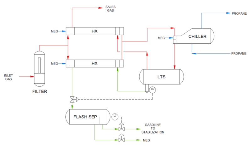
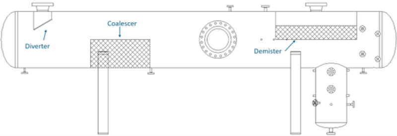
Fig. 2 shows a sketch of the original 44-in. ID×24-ft tangent-to-tangent (TT) vessel used as the two-phase LTS separator. The vessel has an impact plate diverter, a coalescer, and a horizontal mesh pad. The vendor indicated that it would operate properly solely based on liquid residence time considerations.
Change in Operating Conditions
Table 1 shows how requirements of the mechanical refrigeration plant at the previous location compare to those at the present location, with more impact on operating pressure, duty, and hydrocarbon liquid flow.

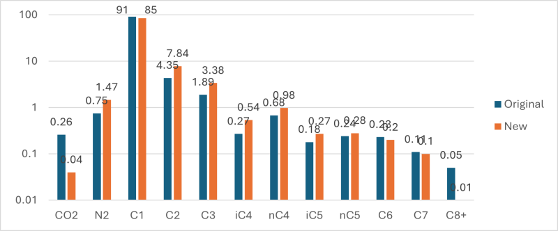
Inlet composition (Fig. 3) also had a substantial change in the C2-C5 region, which impacts directly on the ability to achieve the HCDP.
Plant-Reported Issues
Several issues arose when operating under the new conditions including:
- High HCDP that could lead to losses of USD 125,000 per day for gas below sales spec
- High cooling power requirements
- High hot-oil circulation rate at the condensate reboiler
- Recurrent compressor trips
Based on field tests and process simulation verifications, the above issues were attributed to the LTS design as follows:
- High HCDP, 32°F vs. required 21°F; attributed to carryover from LTS
- High cooling power by the chiller: operators tried to compensate for liquid carryover with lower operating temperatures
- High hot-oil circulation rate: product of MEG carryover causing clogging of condensate reboiler as the flash separator could not sufficiently separate the MEG from the gasoline
- Compressor issue: occasional drains to remove MEG-condensate “emulsion pad” from the LTS and flash separator to the compressor scrubber caused the compressor to shut down.
All these issues appear as symptoms of poor separator performance.
Review of LTS Separator Operation
Analysis of the flow in the LTS separator led to the following conclusions.
- Small droplets are generated due to the high momentum (7500 Pa) impact on the inlet diverter plate and the liquid's low surface tension (6 dyn/cm).
- The separator was designed as two-phase instead of three-phase. Flashing through the liquid control valve causes emulsions in the condensate/glycol/water mixture that cannot be handled by the downstream flash separator. This leads to hydrocarbon contamination in the regeneration system and to the formation of tarlike deposits which can clog the coalescing pack.
- A clogged coalescing pack obstructs the liquid flow and causes distortions in the gas flow pattern.
- A partially obstructed wire mesh pack and its location remarkably close to the liquid surface, combined with lower operating pressure and different fluid composition, result in additional flow pattern distortions and higher gas velocities. This leads to increased entrainment and liquid carryover that has a great impact on HCDP due to the change in composition.
- The flash separator was not properly separating MEG and condensate due to foaming caused by the flashing of the liquid mixture across the LTS level control valve.
Liquid carryover was also estimated using a fluid properties simulator to account for the measured HCDP. Liquid carryover as a fraction of generated liquid vs. flow rate can be seen in Fig. 4. Two different gas compositions, dry and rich, are evaluated at various flow rates and temperatures, showing an increase in entrainment with gas flow rate to match the measured HCDP.
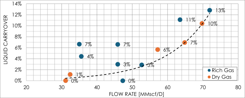
Table 2 compares the results for one case run at 70 MMscf/D between the ideal case without carryover, the impact of carryover on HCDP for the actual measured case, and the impact of lowering operating temperature to try to overcome carryover. The actual HCDP was measured at 30.9°F, and the operating temperature would have had to be lowered to 8.3°F to meet the HCDP requirement.

Because the client could not sell the gas without incurring quality fines, the issues needed to be solved with minimum downtime.
Due to the separator's mechanical and size constraints, no changes to internals, such as the inlet device, the coalescing plates, and the demister, were advisable. Instead, a new three-phase separator was recommended to be mounted next to the existing two-phase one.
New LTS Design and Performance
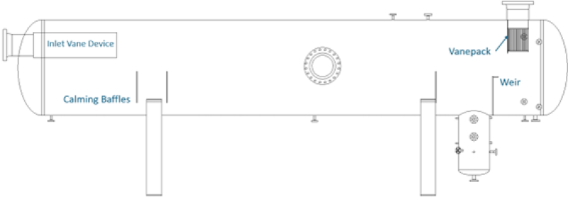
The new design, shown in Fig. 5, allowed the proper location of new internals and the lowering of the vapor section ρv2 to values that, according to our expertise, ensure no entrainment or liquid carryover.
The main upgrades included
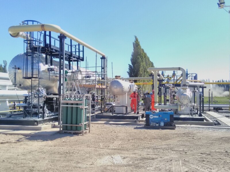
- A three-phase 75-in. ID×32-ft TT separator replaced the original two-phase 44-in. ID×24-ft TT separator. The new vessel is shown in Fig. 6.
- The new inlet nozzle of 12 in., upsize recommended in this case due to inlet piping geometry with several elbows close to the inlet, allowed an inlet momentum of 1500 Pa instead of 7500 Pa for 8 in. Combined with an inlet vane device instead of a diverter plate, this improved inlet droplet size distribution.
- The gas outlet nozzle was upsized from 8 in. to 12 in. to reduce the pressure drop and channeling through the demister.
- No coalescing pack was selected to avoid the negative effect of eventual clogging.
- Three normalizer baffles were included to improve the flow patterns and minimize flow bypass and recirculation.
- The liquid-liquid section was designed for low velocity to allow proper separation.
- A double-pocket V-vane pack with perforated plates to improve flow distribution replaced the wire mesh pad prone to fouling. Cyclones were not an available option.
- An appropriate oversizing of the vessel was considered to cope with the diminishing effectiveness of the V-vane pack due to the high working pressure.
- With the new vessel separating the bulk of the MEG, foaming in the flash separator was eliminated, allowing it to remove the small amount of MEG in the new LTS liquid stream.
After starting the new LTS, the results were immediate. The plant reached HCDP, minimizing compression shutdown, flaring, and propane cooling power. It also reduced the hot-oil circulation rate and overall operational emissions by more than 30% (500 CO2e tons/y), the same as flaring emissions (70 MMscf each day the plant was down).
Final Remarks and Lessons Learned
When adapting existing equipment to a new service, it is imperative to thoroughly analyze the potential impact of different fluid properties, composition, and operating conditions. This requires a deep understanding of how these interconnected variables can significantly influence performance.
While selecting appropriate internals can enhance the separator’s effectiveness, it is equally crucial to ensure that the separator's overall dimensions are well-suited. Neglecting proper sizing over solely adopting internals to minimize diameter and length is never recommended.
The incorrect selection of an inlet device can hurt separation performance of an otherwise well-designed separator.
Wire-mesh mist eliminators or coalescing packs should be avoided whenever the service has potential clogging issues.
For Further Reading
Optimizing Glycol Injection Refrigeration Plants by Mike Sheilan. Presented at the 41st Laurance Reid Gas Conditioning Conference (1991).
The Savvy Separator Series by various authors, 2015 to 2024.


