
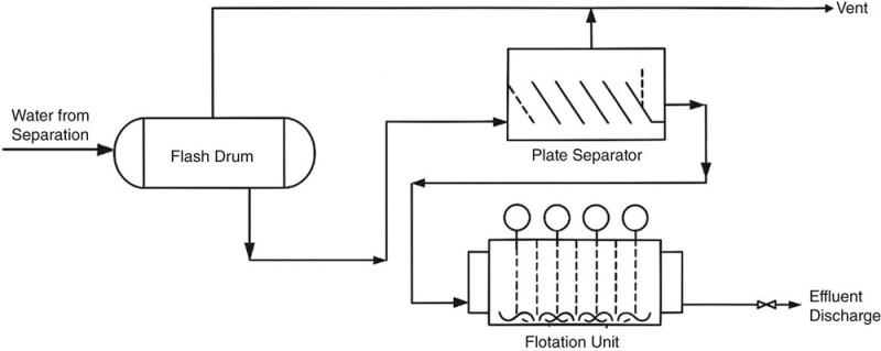
Produced-water degassers—also called flash drums—have been a core component of produced-water-treatment (PWT) trains for decades. They often serve to strip dissolved gas and free oil before discharge (Fig. 1) and/or prior to treatment with low-pressure systems such as plate separators (PS) or mechanically induced gas flotation (MIGF) units. These degassers are more common in the North Sea, Angola, Australia, and Asia than in Gulf of Mexico and Brazil.
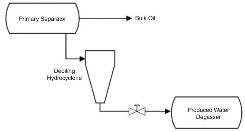
The introduction of deoiling hydrocyclones (DOHCs) in the late 1980s significantly reshaped process flowsheets (Fig. 2), particularly in response to the space and weight limitations of offshore installations. These units typically replaced plate separators and, in many cases, also eliminated the need for flotation units. The degasser was repositioned downstream of the cyclones, as the hydrocyclones require a substantial pressure drop to operate effectively. As a result, oil-contamination levels at the degasser feed were significantly reduced, leading to minimal gravity-based separation or skimming within the unit. However, this created an opportunity to make some gains using gas flotation.
Depressurising the DOHC underflow releases flash gas, typically forming fine bubbles within the produced water and, in some cases, within the oil droplets themselves. These bubbles and gas-lifted oil droplets enhance the deoiling flotation effect, which can be effectively harnessed if the degasser and its internals are designed to maximize this phenomenon. Throughout the 1990s, internals were designed/optimized to exploit this effect, leading to the flotation-enabled degasser: a flash drum fitted with specialized internals that drive gas-assisted oil removal within the vessel’s volume.
In some instances, many plants now position a partial- or full-degassing stage upstream of the hydrocyclones, chiefly to reduce the number of cyclones (and independent control loops) needed when several streams feed the produced-water system. To minimize droplet shear and reduce costs, partial degassing is generally preferred, as it maintains sufficient supply pressure to the deoiling hydrocyclones without requiring booster pumps. However, when upstream supply pressures are low, this approach is not always feasible. The ideal location remains case-dependent—shaped by fluid chemistry, turndown range, layout constraints, upstream operating conditions, and operator preference.
In modern PWT systems, the inclusion of degassers can vary. Their presence depends on various factors such as system configuration, target discharge specifications, and overall design philosophy. Degassers are typically incorporated when discharge requirements are particularly stringent, when downstream components—such as produced-water reinjection (PWRI) pumps—require specific operational conditions like run-up or run-down time, or when the design philosophy mandates three distinct stages of treatment within the PWT system.
This article will highlight some of the key design aspects of a flotation-enabled degasser, followed by case studies of retrofits.
Vessel Design
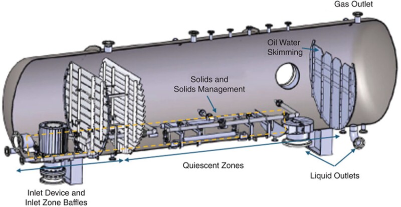
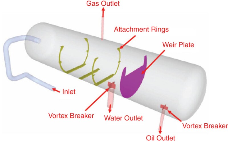
Degassers are available in both horizontal and vertical orientations. While many design principles are shared, degassers are not the same as vertical or horizontal induced gas flotation units. Horizontal degassers (Fig. 3), the default choice where space allows, offer an extended liquid path, allowing breakout gas bubbles more time to disengage and separate from the bulk fluid—and with the right internals—carrying oil droplets with them. Plug-flow behavior can be promoted through baffling. In contrast, vertical degassers, offer a markedly smaller footprint, and on floating production, storage, and offloading (FPSO) facilities, exhibit superior tolerance to vessel motions (provided the vessel diameter is not excessive). However vertical degassing vessels are not commonly used, and the preference whenever feasible is to use horizontal degassing vessels for better performance. The tradeoff is a reduction in the overall separation performance of the vessel, due to both less favorable bubble-droplet transit trajectories and difficulties in isolating the effects of inlet flow from calm zones within the vessel.
Irrespective of orientation, modern practice is to size for a minimum of 1.5 minutes of design volumetric residence time. Experience shows that performance and resilience to upsets improve materially at 3 to 6 minutes, particularly where fluctuating gas rates or slugging flows are anticipated. While shorter residence times have occasionally been observed in brownfield installations, these are not recommended as a basis for new design.
It is typical to see length-to-diameter ratios of 3 to 4 for horizontal vessels with less-concrete values observed for vertical units.
Residence time, however, is only a first-pass metric. Final sizing must also account for bubble-rise velocity, droplet-settling trajectories, bubble-droplet interaction behaviors, host facility motion (if any) and ultimately, the risk of gas carry-under. Basic sizing principles use particle-settling theory; computational fluid dynamics (CFD) can be deployed to validate hydraulic behavior and further improve bubble- and droplet-trajectory estimates derived from settling theory. Performance estimates can be applied based on empirical correlations or semi empirical models tuned to suitable datasets.
Internals and Bubble Generation Technology
The space within a degasser vessel can be divided into sections, each serving a different primary purpose. Fig. 3 above also shows key design zones for a horizontal degasser:
- Inlet device and inlet zone baffles
- Quiescent zones (including oily water skimming)
- Liquid outlets
- Gas outlets
- Sand and solids management
These areas are discussed below.
Inlet Device and Inlet Zone Baffles
The inlet section relies on a momentum-reducing device followed by a full-length liquid holdup baffle. In highly gaseous services a baffle in the gas space may be required to suppress mixing and froth carry-over into subsequent sections. By dissipating inlet energy in a controlled zone, the arrangement establishes a defined region of mixing upstream of the main separation volume, allowing the downstream liquid to remain essentially quiescent. Mixing energy is tuned—not eliminated—to maintain the native bubble-size distribution and to drive bubble–droplet interactions, promote floc formation, and activate any clarifier chemicals dosed upstream. The inlet nozzle can typically be sized more aggressively than in conventional separators because the additional shear risks are reduced because oil-droplet sizes entering the unit are typically an order of magnitude or two lower than within production separator feed streams, making performance-hindering droplet shear less likely.
The inlet device must permit suspended solids to pass freely into the vessel and settle onto the base where dedicated sand-handling systems can remove them. Highly restrictive or enclosed inlet devices are suitable only for demonstrably clean services; otherwise, they trap debris and compromise performance. Likewise, the baffles that divide the inlet and quiescent zones should be configured so that settling particles can migrate through, ensuring the full floor area remains available for solids collection and subsequent removal.
Where a gas blowby (from upstream separators) case exists, the inlet device and baffles should be designed to handle the flow behaviors and retain mechanical integrity. Use of CFD, finite element analysis (FEA), and in some cases, vibrational analysis should be considered. Special attention may need to be placed on the sizing and design of the gas outlet nozzle and any pressure safety valves. The liquid surge created by gas expanding over upstream control valves can create incredibly violent conditions within the vessel.
Quiescent Zone
This zone serves as a calm volume where gas bubbles and associated oil droplets rise, while also providing the holdup required for process control elements or downstream systems (e.g., run-up/run-down for pumps). Motion-damping internals—additional baffles or a plate pack—may be fitted when the host facility is a floating structure. Structured/random packing or mesh coalescers should be used sparingly, as they foul readily.
Level instruments are located in this zone, and separated oil is withdrawn via a skimming weir or bucket with correctly sized notches at the downstream end. Overflow-underflow weir arrangements can be used to manage liquid level, but they must be designed and positioned to avoid solids buildup and still provide surge capacity. There are several other considerations that must be made when considering this type of mechanical level control especially liquid surging previously mentioned; however, this is outside the scope of this document. For reliable performance the vessel should operate with only a thin oil layer, as any significant accumulation can be re-entrained during upsets and sharply increase effluent oil-in-water concentrations.
Liquid Outlets
Liquid outlets should be fitted with capped, multivane vortex breakers and are placed at the downstream end of the quiescent zone, typically beneath the oily-water skim region. The outlets, along with internals and inlets, must be arranged so they do not induce rotating flow; persistent swirl can override even a well-designed vortex breaker and lead to vortex formation.
Outlet nozzles should be placed at the end of the quiescent zone where separation has been completed to the fullest extent possible. This placement can conflict with mechanical design elements such as vessel saddles. If ideal placement is not possible, use of internal piping may be used to locate an effective outlet nozzle at a more suitable location. In vertical vessels, placement such that the outlet flow is symmetrical will reduce short circuiting, offer greater vessel volume utilization, and ultimately improve vessel performance.
Nozzle sizing based on velocity and/or momentum criteria can follow established norms for greenfield or newbuild projects, typically limiting outlet velocities to 2 m/s or less. In brownfield environments, however, higher values are common. In such cases, a more detailed assessment of the system and fluid properties is required to ensure that elevated velocities do not lead to operational issues. It is also important to note that as nozzle velocities increase, the risk of vortex formation rises. Therefore, the presence of a well-designed and properly functioning vortex breaker becomes increasingly critical.
Gas Outlets
The gas outlet is located at the downstream end of the quiescent zone. Demisting equipment can be added when service demands it, but is not always required. If the vessel must tolerate gas blowby, the outlet nozzle is positioned well away from the submerged inlet so that liquid cannot flood the nozzle during a surge, and the nozzle is generally supplied with no demisting internals.
As with liquid outlets, gas outlet sizing for degassers can follow standard norms commonly applied in separator design. However, if gas blowby is a design consideration, particular attention must be paid to the sizing, outlet location, and selection of internal components to ensure proper performance. Additionally, with increased nozzle velocities during gas blowby, the downstream piping design along with proximity of an elbow to the vessel outlet nozzle should be investigated for erosion and for vibration.
Sand and Solids Management
Sand and solids accumulation within degassers is generally less severe than in the upstream production separation train; however, considerable solids can often be found within degassing vessels. Solids can be in the form of reservoir particulates, corrosion products, asphaltenes, waxes/paraffins, and naphthenic salts—all carried under from the upstream separation system. Upstream pressure drop and subsequent outgassing of CO2 can further alter bulk fluid pH, creating opportunities for mineral scale precipitation requiring segregation or chemical mitigation options. The use of some deoiling chemicals can also contribute to the solids problem by binding with oils, fines, asphaltenes, and scales to form sludgy deposits in the vessel. The flotation phenomenon can also lead to many smaller particles being lifted from the water with gas bubbles and thus not constrained to the vessel base or water phase.
Internals within the base of the vessel, designed to allow the gentle fluidization and withdrawal of settled solids and sludge, enable online cleaning. When sludge and fluid deposits are to be removed through vessel drains, high-energy jetting systems should be avoided, as the water will simply disperse the sludge into the bulk flow. Periodic redispersion to transit solids downstream of the degasser can also be a successful strategy. However, several important aspects of the downstream systems must also be considered, but are beyond the scope of this article.
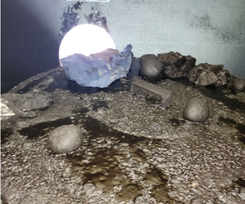
In the event that larger contaminant particles are found or anticipated (e.g., Fig. 4), several well-placed largebore (3 in. or greater) drain nozzles can be provided to periodically remove larger objects to manage accumulation. Jetting or cyclonic desanding systems will be unable to remove large agglomerates such as this. Vessel design including internals must ensure manned entry and access to all “compartments” within the vessel for safe and easier manual cleaning.
Bubble Generation
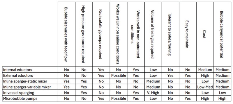
In some cases, the amount of gas liberated through pressure letdown is not sufficient to deliver the desired level of oil-droplet removal through flotation and as such additional gas is required. Additional gas can be injected upstream of the inlet device or within the vessel itself. This approach is not commonly used in conventional degassing vessels and may be applied to retrofit in some systems for improved performance.
Different methods (eductors, inline injection and mixing, microbubble pumps, and sparging rails) can be applied for such solutions, each with different advantages and disadvantages. Table 1 summarizes some key considerations for each approach, but further discussion is beyond the scope of this article.
Case Studies
The following two short case studies on the design, implementation, and operation of degassing vessels as flotation units highlight best practices and lessons learned for technology deployment.
Case Study 1: Minimum Internals Requirements
A produced-water system comprising a DOHC (fed from a primary separator) and a degassing vessel was not operating as required as client rates climbed towards design capacity. The degasser (Fig. 5) was originally intended to degas fluids and remove a residual oil prior to water discharge; however, deoiling efficiencies were minimal and some gas was presented in effluent samples. The internals provided by the OEM were minimal, basic in design, and poorly situated. Some attachment rings were provided for ‘future’ internals installation.
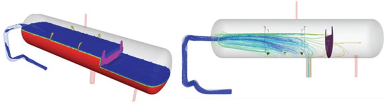
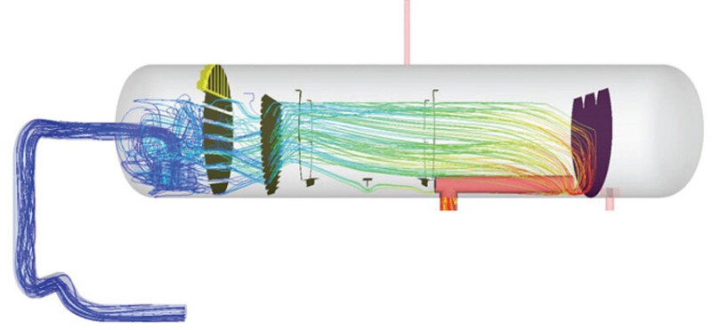
Although the detrimental impacts of the minimalistic internals design and overall arrangement were intuitively obvious, the client needed to provide a greater degree of quantitative certainty to justify the project. The vessel was therefore analysed using CFD study to evaluate flow behaviors and quantify gas and oil-droplet behavior throughout the vessel. For the purposes of this article, two different outputs from the CFD study are shown with the intention of highlighting the care that must be taken when interpreting the outputs from such studies. Considering Fig. 6, the output can show an apparent calmness and positive surface flow pattern (left image) whereas a deeper view (right image) indicates problematic behaviors. The right image clearly shows that primary (inlet) mixing is largely uncontrolled and extends far into the vessel volume. Fluid pathlines highlight flow rotation and short-circuiting to the water outlet.
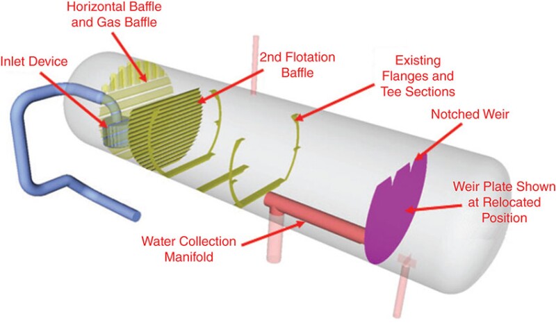
The vessel was also modeled using an upgraded internals design, specifically designed to augment deoiling through gas flotation (Figs. 7 and 8). A submerged inlet device was utilized to provide controlled momentum release gas dispersion, and the inlet zone was completed with a pair of slotted baffles. The second baffle was designed to promote gas-bubble and oil-droplet rise to the liquid surface. The weir plate was notched and relocated further down the vessel. The water outlet was relocated using an internal pipe with integral vortex breaker. Making these changes permitted maximal use of the vessels’ volume while providing a stage of flotation-based produced-water deoiling.
There are several parameters (e.g., residence time, pathlines) that are of interest when analyzing a vessel such as this; however for the purposes of this article our review is limited to residence time as it is an intuitive marker of potential performance. The vessel residence time distributions as predicted by CFD were compared to the theoretical residence time for the vessel (making an assumption that an inlet zone was present). For the original configuration, a theoretical residence time of 1.1 minutes was calculated, and this was compared to an average CFD predicted time of approximately 30 seconds—less than 50% of the available volume was being utilized. For the modified design, the resulting theoretical residence time was increased to 1.5 minutes and the corresponding CFD predicted a similar average residence time (1.3 to 1.5 minutes, 87% or more of the available volume being utilized).
The improvements shown above corresponded to improvements in overall separation performance, both from a degassing and flotation-assisted deoiling perspective.
Key lessons learned:
- Lack of an inlet device and baffling to define the inlet zone meant that primary mixing was not controlled. This was particularly noticeable during process flow upsets.
- No clearly defined quiescent zone meant that utilization of the vessel volume was poor and resulted in low residence times.
- The uncontrolled inlet flow resulted in flow rotation; oil-droplet/sheen accumulation in the center of the vessel far away from the skim zone and re-entrainment of separated droplets were highly likely.
- A poorly positioned weir plate and water outlet nozzle meant that approximately 25% of the vessel volume was unusable for separation purposes (oil compartment did not need to be so large).
- Lack of a suitable vortex breaker on the water outlet made vortex formation probable; telltale signs present in the design and results seemed to confirm this.
- The weir was poorly designed and did not include well-designed skim notches, resulting in difficult precise skimming operation.
- CFD is a valuable tool for evaluating degasser designs, but it should be complemented by experience-based knowledge and semi-empirical performance models to accurately represent the behavior of flotation systems.
Case Study 2: Fouling and Loss of Level Control
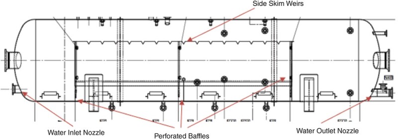
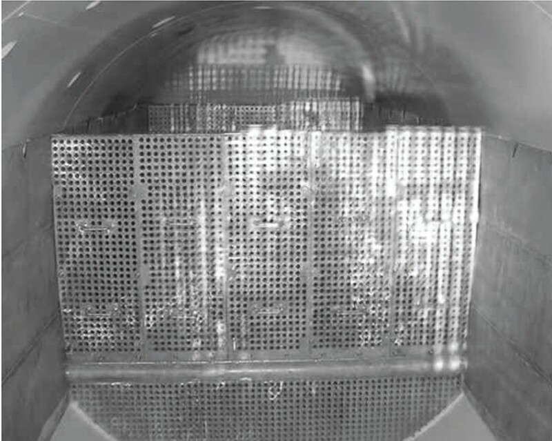
A pair of parallel flow degassing vessels were retrofitted with flotation-enabled internals with the aim of increasing throughput from 57,000 to 70,000 BWPD and reducing the cleaning frequency (2 to 3 weeks) of the current internals. The current system was capable of delivering near-design capacity when in a clean state. The original design (Figs. 9 and 10) did not account for an inlet device, only a submerged inlet nozzle. The internals also included several perforated plate-type calming baffles and side skimming notched weirs on either side of the vessel. Vortex breakers were not provided. The system was originally designed such that future installation of bubble-generation systems could be applied converting the unit into a full-fledged flotation unit. The system suffered from poor performance and blockages of the perforated plates due to the combined effects of drilling muds, chemicals, waxes, and mineral scaling. Liquid-level control (and thus skim control) became difficult as baffle blockage resulted in a significant variance of liquid level throughout the length of the vessel, flooding of the oil compartments, and ultimately degrading capacity and performance.
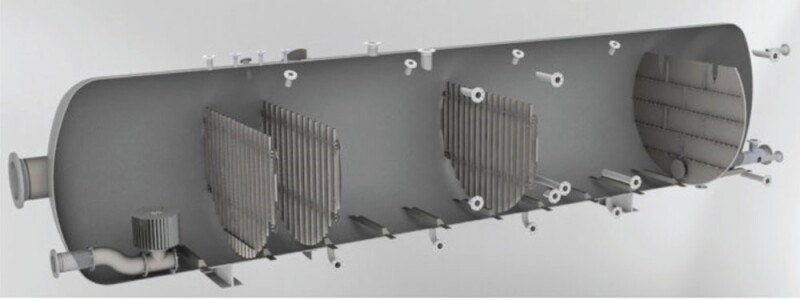
All the original internals were removed with exception of the mounting clips on one of the vessels. As shown in Fig. 11, a new submerged gas flotation-type inlet device, gate/slotted type calming baffles, end-of-vessel skimming weir and vortex breakers (on oily water skim and water outlets) were subsequently installed. A pipe-through manifold was used to connect the head-mounted water outlet nozzle to the clean water side of the newly installed skimming weir.
Past experience with perforated baffles highlighted their sensitivity to fouling, particularly when the perforation diameter is too small. Slotted or gate-type baffles help address this issue by providing larger nominal openings that are less prone to blockage. To further minimize fouling risk, a lower limit is also applied to the overall open area used in the baffle design.
The side weirs were removed and replaced with a single skimming weir located at the end of the separation zone. This modification was driven not only by the objective to optimize skimming efficiency but, more importantly, to ensure that the internals retrofit solution comprised well-established components with a proven history of combined application, precisely integrated to deliver a robust and reliable design.
Internals were bolted for non-welded construction to avoid hot work and costly delays. Following the retrofit, a series of performance tests were undertaken to evaluate the comparative performance of the vessel relative to the original design.
As a result of the upgrade, cleaning cycles were largely eliminated, only to coincide with routine inspection requirements, and both capacity and deoiling performance improved. The retrofitted vessel was able to comfortably process 124% of design capacity (maximum amount of water available) while also delivering performance improvements relative to the maximum capacity of the original design.
Key lessons learned:
- Lack of inlet device meant that primary mixing was not controlled but was restricted to the inlet zone by the initial perforated baffle.
- Baffles were present and did limit inlet mixing to the inlet zone; however fouling and subsequent plugging led to fluids overspilling the inlet zone extending mixing into downstream compartments and the oil compartments (located on the sides of the vessel), ultimately leading to loss of level control. Perforated-type baffles were not well suited to these conditions.
- Generally, utilization of the vessel volume for the purposes of deoiling was poor.
- Vortex breaker was lacking on the water outlet, increasing the risks of gas carryunder and poor fluid hydraulics.
- Installation of a well-designed internal retrofit solution expanded the capacity and performance of the unit considerably, helping optimize existing infrastructure for the purposes of improving environmental performance.
Summary
Degassers can be modified to enhance oily water separation through gas flotation. These modifications require an integrated internals design that addresses bubble generation and use, quiescent settling zones, skimming, and solids management. System dynamics—such as host motion, slugging, or surging—should also be considered to ensure reliable performance. While not covered in detail here, a suitable chemical deoiler system should be incorporated into the design, even if only for managing process upsets.
Editor's Note: This article is the 22nd in a series. To read others, click here.