Gas lift is one of the most popular ways to increase oil-well production, and it is no secret that it is an underperformer.
Back in 2014, ExxonMobil reported that by creating a team of roving gas-lift experts it was able to add an average of 22% more output on several hundred wells where the gas injection had been optimized.
Gains were expected because “wells do not remain the same over time; they change,” said Rodney Bane, global artificial-lift manager at ExxonMobil, in this JPT story covering the 2014 SPE Artificial Lift Conference and Exhibition.
The problem with gas injection is that change is hard. Injection adjustment or repairs require either pulling the tubing to reach the injection mandrels or a wireline run. Those with good-producing wells, particularly offshore, need to weigh the possible gain against the cost and lost production during the job.
Those managing more and more wells live with iffy data, injection systems prone to malfunction, horizontal wells prone to irregular flows, and a time-consuming process for calculating the proper injection rates.
New approaches addressing those negatives have led a few big operators to try new systems designed to allow constant adjustments based on downhole data with electric control systems designed to be more reliable.
Programmable digital controls raise an obvious question: How do you take advantage of that capability? Constantly updated injection data based on traditional evaluation methods is the first step. And new capabilities are inspiring new thinking about how injected gas lifts production and how to make it work more efficiently.
Optimizing the process has not been a priority in gas lift.
“It was a fairly imprecise thing. But the beauty of gas lift is it works even where it’s broken. It’s not a pump; it’s flow assurance,” said Brent Vangolen, surface and base management technology manager with Occidental.
Occidental is among the early adopters of new gas-lift methods along with companies including Chevron, Shell, ExxonMobil, Petronas, and ADNOC.
Vangolen expects the industry will follow. “Gas lift is going through the same transformation as rod pumps went through in the 60s and 70s,” he said. Back then, rod pump engineers began tracking changes in the load on the rod through each pump stroke by using dynamometer cards. That data was used to better program pump controls.
“You went from egg timers on pumping units to full-blown optimization pumpoff controllers, variable speed drives … this huge infant technology that changed the rod pump space,” he said.
Papers at last year’s SPE artificial lift conference covered the continuing digitization in rod lift and that gas lift was finally moving in that direction.
Chevron reported on its testing program for a new gas-lift system that is wired to a digital surface control unit using data from sensors at the injection sites to adjust where and how much gas is injected. The paper said the system enhanced the “operability and profitability of gas-lift wells,” but did not provide any numbers (SPE 201140).
Explanations of how gas lift works are evolving. A quick definition: injecting gas reduces the density of fluids in a well. Those lighter fluids make it easier to lift oil and water.
Some people are now trying to understand how gas lifts fluids by applying multiphase models to make lift more effective and broaden what it can do.
Those selling new injection systems offer positives that do not require the understanding of anything so esoteric. Those range from systems that deliver all the compressed gas to the point where it will do the most good, to real-time data streams that allow engineers to automate systems’ reactions to changing flows in many wells.
“There is a limited number of wells that one person can surveil. These models take 3 or 4 hours apiece to do properly,” Vangolen said.
The number of wells per engineer is high in unconventional plays, and those fast-changing wells demand more attention. “What used to happen in years, now takes months,” according to the Chevron paper.
Shell reported in its paper at the conference that independent operators in Oklahoma pulled more than 100 gas-lift completions in a year to update the gas-lift design (SPE 201124).
Shale wells are a motivator, but the benefits are more widespread. The Chevron paper said that “remotely operated gas-lift valves present a significant opportunity to improve well performance regardless of the development being unconventional or conventional.”
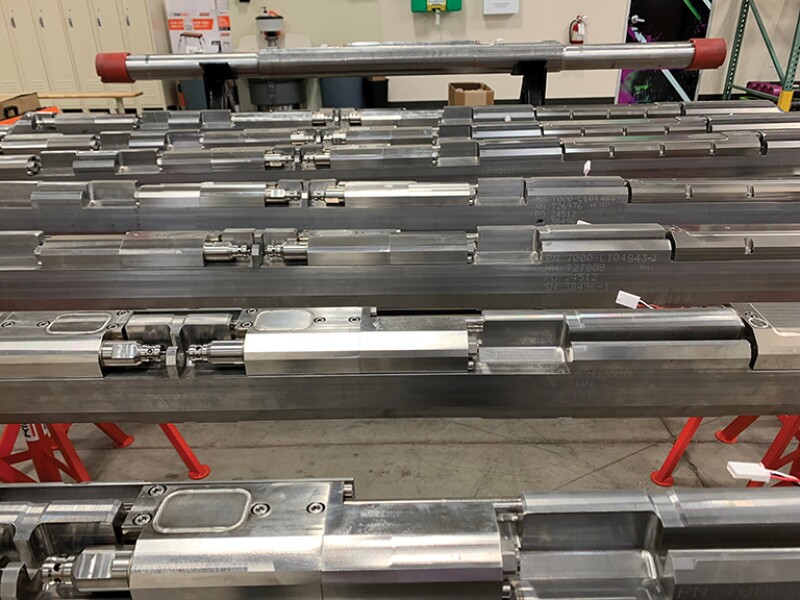
An Electric System
The most tangible difference in the new downhole hardware are lines running from a surface control unit to the
gas-injection points. They deliver power to electrically actuated valves, carry signals to the electric actuators opening and closing the valves, and transmit data uphole from pressure and temperature sensors.
There are common features in new and old systems. In both, gas from a surface compressor flows down to a series of increasingly deep injection points.
The multistep process ultimately reduces the fluid density at deeper and deeper levels to lower the injection pressure required at the deepest point. That limits the compression capacity required at surface to inject near the bottom of the vertical section of the well.
Most of the gas-lift systems have mechanical controls that open and close based on pressure changes.
“Normal gas-lift systems have 25-psi increments in between the valves, so the reservoir and subsequent flowing pressure from hydrostatics and friction must decrease by 25 psi to force gas into the deeper valve. If you are in between these values, the gas can shift and become unstable, causing valve chattering and premature failure,” Vangolen said.
Erratic flow can be particularly troublesome in shale wells. Long, torturous laterals work like a gas separator, leading to intermittent flow patterns that can confound mechanical valve controls.
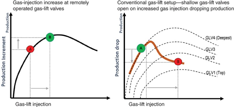
A chart in the Chevron paper showed how an open valve at a high level could reduce the production benefit to not much more than would be seen without gas lift.
Traditional gas-lift designs are created while planning the completion. They rely on rules of thumb to estimate the density at each injection point and how much gas will be needed to reach target drawdown level.
Data from new systems show wells are not so predictable. Based on the downhole pressure and temperature data gathered by Chevron, its estimate of the specific gravity of the fluid was off by 12%. Its paper said the estimate failed to account for the high level of gas condensate in the referenced Permian play.
Interested but Not Buying
A barrier to most innovations is oil companies are reluctant to commit the money and time needed to change. New gas-injection systems are no exception.
“We make no bones about it is more expensive than conventional gas-lift systems in the Permian. It is a fundamentally different thing. It is data-driven, and you do not have to do all that intervention,” said Graham Makin, vice president for sales, marketing, and investor relations at Silverwell Energy.
He recalled a gas-lift expert who told him that a handful of other companies had tried to commercialize such a system, but Silverwell was the first to sell systems used in wells at a price that has attracted a group of big early adopters.
Oracle Downhole Services, a Canadian company, originally designed its system for enhanced oil recovery injections, which Occidental realized was functionally similar to gas-lift injection and cost less.
As is often the case, innovators that have paid the cost of developing and proving a new idea run into resistance from oil industry buyers who balk at paying more for a new system.
Makin counters that over the life of the well, these systems can add production by constantly adjusting the injections based on real-time data and without the cost of well interventions.
Because these systems can be monitored and maintained remotely, Silverwell’s users have also reduced the time and risk involved with wellsite visits and well interventions.
Longer-term data could open the door for performance improvements based on digital analysis.
So far, most companies in the industry are waiting to see if these efforts are worth doing.
“I think the industry is very young right now,” Vangolen said. While there are not many users, “there is a lot of interest in it.”
Silverwell is working with a handful of clients around the world, including Petronas in offshore Asia, ADNOC in the Middle East, and Chevron for onshore unconventionals, to “demonstrate the value of digital analysis and control,” Makin said.
After years of work, the number of Silverwell-equipped wells is still in the low double digits, but Makin expects “we are at the start of a hockey stick moment.”
The company highlights the reliability of its actuator design. While the downhole wiring presents technical challenges, the combination of data and surface control simplifies the writing of control and automation software.
Vangolen said they were able to outline one such program in three loops on a white board, adding, “It is relatively easy to do that if you have the real-time information.”
Bubble Size Matters
Anand Nagoo is a lift engineering consultant who sees opportunities in digitally controlled gas lift.
While Chevron’s paper referred to programming based on widely used gas-lift software, Nagoo sees a lot of room for improvement.
“Basic modeling is not enough to reproduce the multiphase flow behaviors that affect gas-lift performance,” said Nagoo. While companies like Silverwell work to create automated gas-lift control systems, he is thinking about ways to make the software more sophisticated.
“The prize here is to identify the different multiphase flow mechanisms that dictate the optimum performance,” Nagoo said. For example, the injection strategy for low gas/oil ratios needs to be different from those with much higher gas/oil ratios, he said.
While he sees the new control systems as a significant step up, his plans do not assume users will have them.
A lot can be done using data from a downhole pressure gauge, accurate tables, and an understanding of the minimum gas rates needed for lift—the critical rate—plus well and production data, and some information from third parties.
The phrase that comes up over and over is “multiphase flow.”
“There is more data on multiphase flow than on [gas-lift] field results,” said Nagoo.
Nagoo is working on both simplified reference tables for calculating injection rates in various types of wells and building that information into new software for calculating the critical gas-injection rate needed for effective lift.
The interactions between rising gas and liquids in gas lift are a form of multiphase flow. And there is a lot more multiphase work out there to draw on.
A paper that was a collaboration between Vangolen and Nagoo looked at how wells with long laterals affect gas-lift performance (SPE 201403).
Deeper is better when installing lift systems in the vertical, but that does not extend to the lateral. What flows through the well there behaves differently because that long sideways tube looks and acts like the horizontal tanks in a gas/liquids separator.
Faster-moving gas collecting at the top of the pipe can slip past the liquids. One phase slipping by another is a defining characteristic in multiphase flow. For that reason, if the lowest gas injector is below 45°—halfway in the curve from vertical to horizontal—Vangolen and Nagoo’s paper warns that gas slipping is likely to reduce the effectiveness of the gas lift.
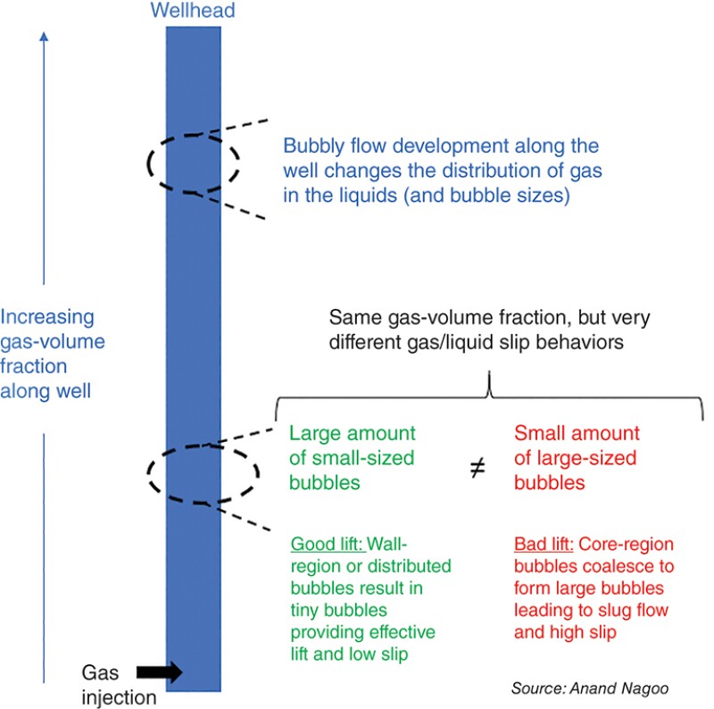
Gas lift remains focused on overcoming the force of gravity in the vertical. Nagoo said it does that most effectively when the gas is in the form of tiny bubbles concentrated near the pipe walls. Smaller gas bubbles are more efficient at dragging droplets of water and oil to the surface.
Bubbles concentrated near the middle of the well are likely to be larger and are more likely to combine with other bubbles leading to slugs, which are prone to slip past liquids and have reduced lift capacity.
Nagoo said while slugs are not all bad (some types can efficiently transport liquids), they can be “really bad news.”
Experiments, like one at Louisiana State University (LSU), have taken high-speed videos showing there are different types of gas flow.
Unfortunately, even when gas-lift systems create concentrations of the effective tiny bubbles near the walls—like those in a champagne flute—things change on the long trip to the wellhead.
That results in inefficient gas lift with less liquid produced per million cubic feet injected. There is no tool for observing bubble flow in producing wells. The volume of gas injected does not answer the question.
Differences can be caused by the injection pressure, the mix of gas and fluids, the water cut, the amount of gas coming out of solution, and the friction caused by the size of the tubing. All can alter the well’s ability to create “a turbulent liquid that is acting as a microbubble breaker.”
Vangolen said the turbulence created by the injection can help create small gas bubbles that can efficiently transport oil and water up to the surface. But as it travels upward that phase can change.
A paper Nagoo posted on his LinkedIn raised the possibility of adding hardware in the well to sustain the bubbly flow.
“Gas-lift valve placement along the flow path should result in improved control” of the wall-hugging bubbly flow.
Another option would be placing devices at multiple spots along the flow path that would cause a reduced bubble size and result in improved control of the bubble size.
Just injecting more gas would seem like an obvious fix. But the paper cited an experiment comparing a fluid with a low-average gas concentration and one with a higher gas concentration.
The test showed the one with the lower gas concentration had more of the active, tiny bubbles along the well wall.
Some Counterintuitive Thinking
Compressor capacity limits have a major influence on gas-lift designs. Injecting gas requires stepping up the pressure high enough to reach the critical velocity required to overcome the pull of gravity.
As wells age and the flow takes on more water with less natural pressure behind it, the challenge becomes greater and greater until the well stops producing altogether.
Bigger compressors can do more, expanding the role of gas lift earlier and later in the lives of wells. But as wells age and the natural pressure and production potential drop, paying more for compression capacity is a tough sell.
New injection systems are built to use compression power more efficiently, cutting waste by ensuring they can direct all the compressed gas to the zone where it is needed most.
And then there’s an idea out there that promises to extend what a typical compressor can do by three or four times.
At last year’s artificial lift conference, Paulo Waltrich, an associate professor at LSU, presented a paper reporting the results of a successful test of the method that injected fluid and was followed by gas to sweep out a water-filled 2,800‑ft test well and kick off gas lift in less than 2 hours using a compressor whose design limit was 800 psi.
It was not the first such paper by Waltrich, who is also the chief technology officer for Lift Well International, which is trying to commercialize a method based on research at LSU started by Shell over 10 years ago.
The idea is that by starting with water injection before injecting gas, it is possible to sweep out fluids more efficiently than with gas alone. It is conceptually similar to enhanced oil recovery methods that alternate water and gas injections, and it is hard to pull off.
Outsiders see the added water increasing the density of the well fluid, which is the opposite of what gas lift is trying to accomplish.
“It’s counterintuitive; I have heard that as well. So that is why some people are afraid to do it,” Waltrich said.
Another barrier, he acknowledges, is that others have tried and failed to do it.
“We failed many times before we could succeed,” he said. “We tried to do it and it didn’t work as we kept trying for several years. If you do not know the trick, you will fail.”
The trick behind the method known as liquid-assisted gas lift (LAGL) is in controlling the pace of the transition from all water to all gas, and in the injection pressures. The initial water-injection phase allows the reduction of the water level in the well to where normal gas injection can be used, Waltrich said.
A digital unit starts with the water injection that kicks off the flow into the well, increasing amounts of gas added and the small bubbles needed to efficiently lift the liquid.
Those claims were tested when the company went through the Shell GameChanger program, which selects a few ideas among thousands with a goal of moving those ideas toward commercialization.
In a test at a 2,800-ft research well at LSU, this method was able to clear a water-filled well in 2 hours with a maximum compressor pressure of 535 psi. That was followed by a computer-controlled test, where the water-filled well was cleared out in 1 hour and 24 minutes with a maximum pressure of 724 psi.
Lift Well has developed an automated control system to control the injections, but Waltrich said that is the only specialized equipment required. Rather than a gas-lift valve system, they say their method makes it possible to inject down production tubing and have it U-tube back up the annulus or vice versa. A check valve can be added if water loss in the reservoir is an issue.
Without the water boost, the pressure required to inject at the depth where the annulus can flow into the tubing is beyond the capacity of compressors commonly found on well pads.
In a 10,000-ft well producing 300 B/D of oil, the liquid assist could unload the well with about 700 psi in compressor pressure, compared to about 4,500 psi if single-point injection were used, the paper said.
In that test, Shell used an injection control valve it designed to work along with a packer in an offshore well. It said the single-valve system would save money compared to a more complex system injecting at multiple depths.
“LAGL utilized a single gas-lift valve, which reduces system costs compared with the traditional use of multiple valves and mandrels, while also reducing the risk of tubing-to-casing leaks,” the paper said.
The big challenge here is convincing people in the industry that they will get out the water that they put in.
Vangolen’s estimate of the water needed is many times greater than Waltrich expects. For example, Waltrich said that in a 10,000-ft well, the water injection would be replaced by gas lift in 10 hours. During that period the water used would be recirculated, further reducing the amount required. Vangolen counters that a well producing a lot of water is not like a test well filled with water at the start.
George King, principal at GEK Engineering, said, “It could work in the right tubing and casing configuration.
“The water volume is probably calculated and controlled to be the same as the small annulus volume where the length of the water column (not the volumes) is longest. The water head compresses the gas, and if the well tubing and casing is properly configured, the gas will lift more liquid volume than the water volume injected into the annulus,” King said.
In Waltrich’s 10,000-ft well example, those volumes are equal at 230 bbl each.
King also said it would likely require several water-injection cycles to effectively unload the water in the well, while Waltrich said it could be done in one cycle.
Given the questions and confusion about what they are doing, field tests results will be critical. Tests were planned last year but fell through after the COVID-19 pandemic shut down travel and nonessential field operations.
Waltrich said they are working to test soon in a well near the Texas-Oklahoma border where the operator wants to see if the method is a workable substitute for pumping using an electrical submersible pump (ESP).
If it works, gas lift might be an alternative to ESPs. Operators often use these high-capacity pumps early in the life of wells when production of oil, and often water, is high.
They would like to find an alternative to ESPs, which are expensive, high-performance machines that are typically replaced by another form of lift after a year or so—most-often by gas lift— because fast-falling production and rising gas levels present problems for ESPs.
Gas lift from the start could be a money saver, but change is far from certain. Waltrich has learned it is “very hard to get people to think differently.”
For Further Reading
SPE 201140 Pilot Application of Remotely Operated Gas Lift Valves in Permian Basin Unconventional Wells by Johannes Visser and Tomislav Basic, Chevron.
SPE 201124 Full-Scale Validation Test of Liquids Assisted Gas Lift LAGL by Amanda M. Scott, Stuart L. Scott, Petroleum ETC; Brian J. Schwanitz, Welltec; and Steven Freeman, Shell.
SPE 201403 Will Gas Lifting in the Heel and Lateral Sections of Horizontal Wells Improve Lift Performance? The Multiphase Flow View by A.S. Nagoo, Nagoo & Associates and Brent N. Vangolen, Occidental Petroleum.
Getting more out of gas lift requires understanding how gas injections interacts with the oil, water, and gas flowing up the well. In other words: multiphase flow. Here are additional papers to get you started: Diving Into Multiphase Flow.