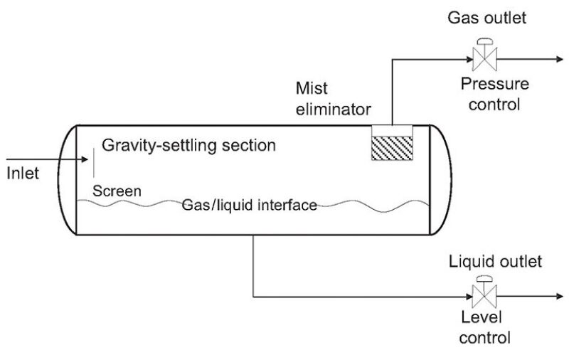
The sizing procedures for all of the process equipment in the oil and gas industry share a common assumption: The stream flow rate measured at the inlet is always constant or stable. This principle works fine for plants where the process conditions are controlled, but it does not apply to primary production facilities where the streams come from multiphase flowlines or wells. The sizing procedure described in the paper allows one to size horizontal gas/liquid separators considering nonstable flow rate at the inlet or fluctuations in the liquid fraction on the same stream.
Background
From a design standpoint, separators are split into three stages (or sections).
Primary Stage. This is a mechanical operation; it uses an inlet diverter so that the momentum of the liquid in the gas causes the largest droplets to impinge on the diverter, forming droplets that are separated by gravity. The gas stream flows to the disengagement section.
Secondary Stage. Liquid drops immersed in the gas stream are separated by gravity. This separation is governed by the settling liquid-drop velocity inside the gas phase. This velocity must be higher than gas-stream velocity to allow the drop to settle to the liquid phase.
Tertiary Stage. This occurs on the mist eliminator. This is a device that allows small-sized droplets to coalesce to larger drops, which fall down by gravity to the liquid phase.
These design stages or sections are shown in Fig. 1 above. The primary stage is designed on the basis of a simple volumetric balance, following some well-known rules. The most important parameter to consider in designing the secondary stage is the settling drop velocity inside the gas stream. This velocity can be calculated by performing a balance around each liquid droplet. This balance takes into account two factors, gravity and the drag forces applied by the gas stream. Liquid droplets settle at a constant velocity known as terminal velocity (for its calculation, as well as a discussion of the theoretical model used, please see the complete paper).
Holdup and Surge Separator Volumes
According to Svrcek and Monnery (1993), separator holdup is defined as the time it takes to reduce the liquid level from normal (NLL) to empty (LLL) with a constant outlet drain rate and a closed inlet. Holdup is the capacity to keep a constant outlet flow rate without interrupting the inlet flow rate. On the other hand, surge is the time it takes to raise the level from normal (NLL) to maximum (HLL), with a constant inlet flow rate and a closed outlet stream. Surge is the capacity to accumulate liquid if the outlet stream is closed and the inlet is open. There are several recommendations to state the holdup and surge times. These definitions work well for process vessels or balance tanks but not for primary oil/gas separators. To apply the Svrcek and Monnery procedure, some redefinitions are made. The holdup time is replaced by the residence time. This parameter ensures gas/oil separation in the primary stage. For foamy oils, the residence time can be increased up to 15 minutes. Residence times between 2 and 5 minutes are common for all the separators in the field.
Surge Volume for Nonstable Multiphase Streams
In primary separators in which the feed comes from wells or multiphase flowlines, slugging can occur. As a consequence, the feed flowrate exhibits a nonstable behavior; the liquid fraction at the separator inlet fluctuates over time. This violates the sizing-procedure basic assumption, which is steady flow rate at the inlet. To adapt the Svrcek and Monnery procedure to nonstable streams, surge volume is redefined. Surge volume is the maximum liquid accumulation in the separator at constant outlet drain rate. This volume is reserved to catch and damp the slugging occurring in the inlet stream. The objective is to design a separator according to the residence time and gas-disengagement-section design rules. To perform the surge-volume calculations, a dynamic multiphase simulator is needed. A detailed description of liquid- and gas-flow rates feeding the separator is required.
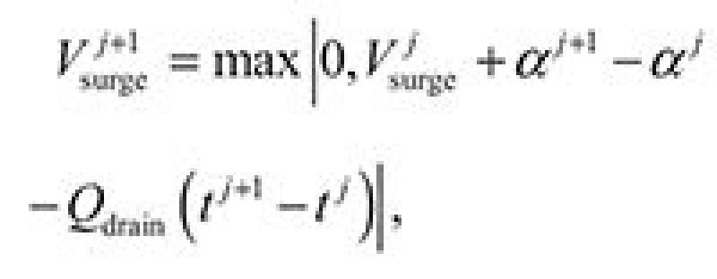
The maximum accumulation, defined as the surge volume, is given by:
| ........... Equation 1 |
where Vsurge is the surge volume, α is liquid accumulation measured at a fixed position (typically the flowline outlet), and Qdrain is the constant outlet separator drain rate. Surge volume can be estimated on the basis of simulation results and it is usually reported in curves. Surge volumes make sense for drain flow rates higher than the average liquid flow rate measured at the flowline outlet.
Sizing Procedure for Nonstable Multiphase Streams
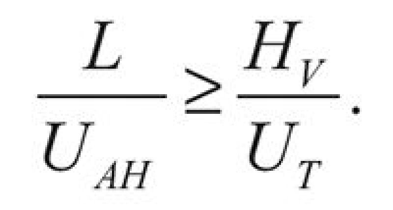
This procedure was initially described by Svrcek and Monnery (1993) and was applied to size separators in process plants. The modification presented in the complete paper adapts the procedure to separators handling nonstable streams. In horizontal separators, the liquid droplets are influenced by a drag force in the horizontal direction; this force is not opposed to gravity, as is the case with vertical separators. As a consequence, the horizontal velocity is greater than the terminal velocity (in the vertical direction). Liquid-dropout time needed to traverse the horizontal separator distance must be higher than the settling time in the vertical direction:
| .......... Equation 2 |
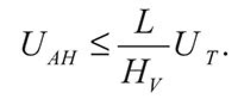
Eq. 2 can be rewritten explicitly to the horizontal velocity:
| .......... Equation 3 |
Usually, the L/HV is greater than unity for horizontal separators and the terminal velocity must be corrected. Theoretical models or Arnold’s model is recommended to calculate the terminal-velocity constant. Values obtained by use of these models are more conservative than others cited in the literature. This sizing procedure is iterative; the separator diameter is not calculated explicitly. For this procedure, the design input data are the mass-flow rates and fluid properties. These equations can be adapted easily to the volumetric-flow rates available in the field. Actual flow rates are required, not standard flow rates measured at stock-tank conditions. This rule must be applied to gas and liquid densities.
1. Calculate the volumetric gas-flow rate:

| .......... Equation 4 |
2. Calculate the volumetric liquid-flow rate:

| .......... Equation 5 |
3. Calculate the gas terminal velocity, UV=0.75 UT, for a conservative design.
4. Calculate the holdup volume on the basis of residence time:

| .......... Equation 6 |
5. Calculate the surge volume on the basis of dynamic simulation results.
6. Obtain an estimate of separator diameter:

| .......... Equation 7 |
Round to the nearest 6 in., and calculate the cross-sectional area with

| .......... Equation 8 |
7. Calculate the minimum liquid level on the basis of Table 1.

| .......... Equation 9 |
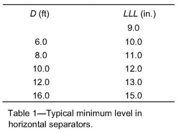
where D is in ft and rounded to the nearest inch. If D≤4.0 ft, then HLLL=9 in.
8. On the basis of HLLL/D, calculate ALLL/D (please see Table 4 of the complete paper for more information on this step).
9. Calculate HV. If there is no mist eliminator, the minimum height of the vapor disengagement area (AV) is the larger of 0.2D and 1.0 ft. If there is a mist eliminator, the minimum height of HV is the larger of 0.2D and 2.0 ft. Calculate AV on the basis of HV.
10. Calculate the minimum length to contain holdup and surge volumes:

| ......... Equation 10 |
11. Calculate the dropout time.
| ......... Equation 11 |
12. Calculate the actual gas velocity.

| ......... Equation 12 |
13. Calculate the minimum required length for the gas/liquid disengagement section:

| ......... Equation 13 |
14. If L<Lmin, then L=Lmin. Gas/liquid separation is the controlling parameter; this results in some extra hold-up volume.
If Lmin>>L, then increase HV and repeat from Step 9.
If L>Lmin the design is acceptable.
If L>>Lmin, holdup is controlling the design; L can only be decreased and Lmin increased if HV is decreased. HV may be decreased only if it is greater than the minimum depicted in Step 9. Calculations would be repeated from Step 9 with reduced HV.
Calculate L/D. If L/D is greater than 6.0, increase D and repeat from Step 6. If L/D is less than 1.5, decrease D and repeat from Step 6.
15. Calculate shell and heads thickness and wall thickness (please see Tables 5, 6, and 7 of the complete paper for resources to complete this step).
16. Calculate the approximate vessel weight:

| ......... Equation 14 |
where AS and AH are shell area and head area, respectively.
17. Increase and decrease the diameter by 6 in.; repeat the calculation until L/D ranges between 1.5 and 6.0.
18. With the optimum design (minimum weight) calculate normal and high liquid level:

| ......... Equation 15 |

| ......... Equation 16 |
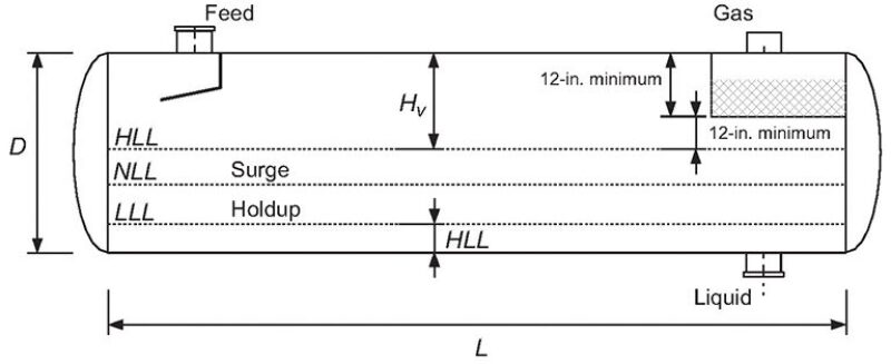
Calculate ANLL on the basis of HNLL. Separator dimensions are shown in Fig. 2.
Case Study
The procedure depicted here was used to size a separator for an oil field located in the Gulf of Mexico. (Please see Table 8 of the complete paper for input data.)
Results and Discussion. A nonstable flow rate is observed in this flowline. Hydrodynamic slugging was identified by the dynamic multiphase simulator. A slug-tracking algorithm was used to calculate individual slugs generated in this flowline. Four cases were analyzed. In the first, the surge volume is neglected. In the additional cases, the surge volume was calculated for a constant drain rate. Table 2 shows the surge volumes calculated for a drain rate that is 1.0, 1.2, and 1.4 times the average total liquid-flow rate, measured at the separator inlet. Separator sizes for the analyzed cases are shown in Table 3.

The volume increases approximately 52% if a drain rate equal to the average total liquid-flow rate is used. This increased volume is reduced if the drain rate is increased. The drain rate cannot be increased arbitrarily; it is a function of the facilities downstream from the separator. A rule of thumb states that a drain rate 20% greater than the average total liquid-flow rate is acceptable for design purposes. If a drain rate 1.2 times the average total liquid-flow rate is used, total vessel volume increases 13%. If a 1.4 factor is used, the total vessel volume increases 9%; this is a marginal reduction in the vessel size. A 1.2 factor seems to be optimal for this design. The separator sized following this procedure will efficiently handle the slugging generated in the multiphase flowline.
For nomenclature for the equations, please see the complete paper.
Reference
Svrcek, W.Y. and Monnery, W.D. 1993. Design Two-Phase Separators Within The Right Limits. Chem. Eng. Progress 10: 53–60.
This article, written by JPT Technology Editor Chris Carpenter, contains highlights of paper SPE 169444, “A Method To Size Gas/Liquid Horizontal Separators Handling Nonstable Multiphase Streams,” by J.L. Hernandez-Martinez, Pemex, and V. Martinez-Ortiz, Schlumberger, prepared for the 2014 SPE Latin American and Caribbean Petroleum Engineering Conference, Maracaibo, Venezuela, 21–23 May. The paper has not been peer reviewed.

