
It is well known that liquid loading in unconventional gas wells can dramatically reduce production and lead to premature abandonment. Liquid loading creates a “vicious cycle” that occurs when liquid blockage creates backpressure in the wellbore or pore space in the formation, resulting in reduced gas velocity and leading to more liquid accumulation over time.
Electrical submersible pumps (ESPs) and other artificial lift technologies are typically unable to remove liquids in both the vertical and horizontal sections of the well.
A new downhole compressor solution, based on advanced magnetic technologies, was developed by Upwing Energy and recently completed its first field trials in an unconventional gas well operated by Riverside Petroleum. Analysis of results during the trial revealed a 62% increase in gas production and significant increase in liquid production over its steady-state performance using a rod pump prior to the subsurface compressor system (SCS) installation.
Subsurface Compressor System
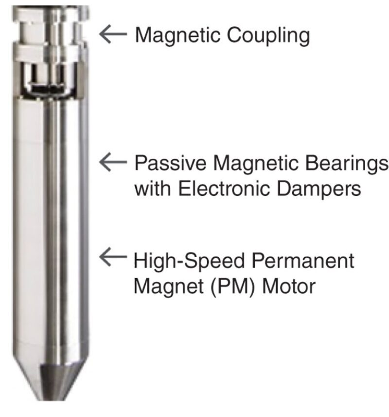
The SCS is designed to provide reliable performance in the downhole environment by eliminating the common points of failure in conventional ESPs. It is based on proven magnetic technologies used in topside and subsea oil and gas applications (Fig. 1), which were deployed downhole successfully for the first time during the Riverside trial, including:
- A high-speed permanent magnet (PM) motor
- A shaftless magnetic coupling between the motor and compressor
- Passive noncontact magnetic bearings with electronic dampers
A sensorless wide-frequency variable speed drive at the surface controls the motor at speeds up to 50,000 rpm via a long stepout.
The hybrid axial wet-gas compressor is driven by the hermetically sealed high-speed PM motor. Torque is conveyed from the motor to the compressor with no mechanical shaft or seals, eliminating the need for a motor protector to isolate the motor from downhole fluids. This “protector-less” architecture eliminates a frequent source of vulnerability for conventional downhole artificial lift systems.
The SCS lowers the bottomhole well pressure, increasing the velocity of the gas stream, removing liquids from the vertical and horizontal sections of the well, and preventing vapor condensation by increasing the temperature of the gas when exiting the compressor. Decreased backpressure from liquid loading results in increased gas production, which in turn accelerates liquid unloading. Once the liquid is carried by the gas stream, the lower pressure at the compressor intake and the higher temperature at the compressor discharge prevents vapor condensation and enhances the carryover of liquids to the surface by the gas stream.
Field Trial
The SCS was deployed in an unconventional shale gas well owned by Riverside Petroleum in Indiana. The trial period started at the end of October 2019, and the SCS was removed in early December.
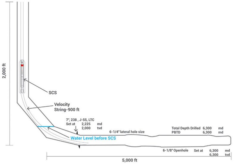
The well has a 2,000-ft vertical wellbore and a 5,000-ft horizontal wellbore, where liquid had accumulated (Fig. 2). The compressor was installed at the bottom of the vertical section with a tail pipe extending approximately 1,000 ft into the horizontal section to provide sufficient velocity to carry liquids while minimizing friction losses. A shroud was used to be able to carry the extended length of the tail pipe.
Prior to the SCS installation, the well was killed with additional water poured down the wellbore to ensure a safe deployment. Once the existing rod pump unit was pulled out, it took 2 days to install and start the commissioning of the SCS in the wellbore. The installation is very similar to ESP systems in that the SCS unit is tubing-deployed, and the electrical cable with the instrumentation was secured around the tubing. In order to maximize the effect of the SCS, a 3.5-in. production tubing along with a 3.5-in. velocity string were selected to provide enough velocity to carry liquids while minimizing friction losses.
Prior to installing the SCS, the production of the well was about 185,000 scf/D, and its liquid production (via rod pump) was 5–7 B/D. Without the rod pump, the well choked within in a few hours.
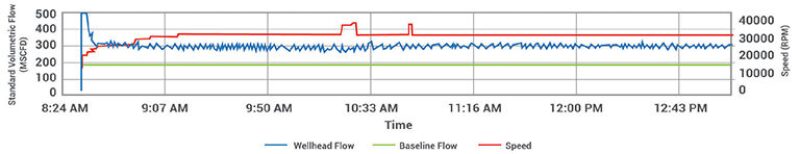
With the SCS, the well stabilized at a gas production of 300,000 scf/D (+62%) with the help of nitrogen injection to kick off the well over a 2-day period, and liquid production increased to over 9 B/D (+50%) over the same period. The nitrogen injection helped push the liquids within the vertical and horizontal wellbore into the formation and enabled the SCS to start up without being submerged in kill fluid.
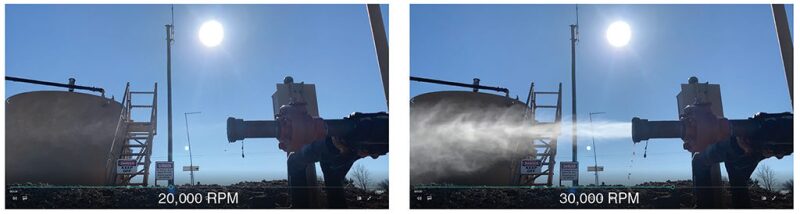
The Turner et al. (1969) correlation assumes that free-flowing liquid in the wellbore forms droplets suspended in the gas stream with gravity force pulling the droplets down and the drag force lifting the droplets upward. The minimum required gas velocity to lift liquids to the surface is 22 ft/sec. While the SCS operated at 20,000 rpm, the gas velocity within the vertical wellbore was 22.5 ft/sec, and the well operated in the transitional state between the slug and annular-mist flow conditions. The liquid production at the surface during that time was detectable although intermittent. When the SCS operated at 30,000 rpm, the gas velocity increased to 29 ft/sec, and a high rate of liquid was carried to the surface (Fig. 3).
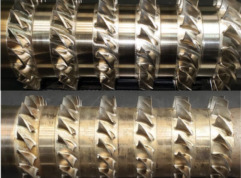
As shown in Fig. 4, the hybrid axial compressor was able to atomize the liquid into a very fine mist, which together with the increased velocity and heat generated from the exit of the compressor helped carry the liquids to the surface.
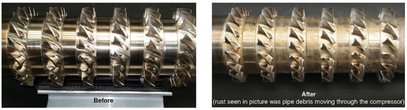
The system was carefully inspected after removal. The hybrid compressor, which had six stages of Inconel rotating blades, showed no sign of wear or impingement due to the liquids (Fig. 5).
The design point pressure ratio of the compressor at 30,000 rpm was 1.25, and this was validated by the downhole memory gauges that were placed at the suction and discharge of the compressor.
Lessons Learned
- The method of killing the well and ensuring that gas did not flow during the deployment was critical for safe operations. In this case, the well was killed with water and the flow through the SCS was eliminated during run-in with the use of a plug above the compressor outlet.
- A double rig is preferable for deployment. During the initial deployment, a readily available single rig with Foster tongs was utilized. Although this worked well, deployment time could have been reduced with a double rig. In addition, the use of open-face tongs would have also reduced rig time by minimizing the management of cables to prevent damage.
- The completion design is as important as the compressor design. The production tubing diameters, velocity string length, and the location of intake(s) on the tail pipe extending within the horizontal wellbore need to be considered during the SCS modeling. Upwing has developed an in-house analysis tool that incorporates and iterates the reservoir, wellbore, topside constraints, and compressor capabilities to optimize the overall application.
- More fluids were produced than what was measured. This was mostly due to the fine mist created by the compressor (liquids being atomized by the multistage wet-gas compressor), which required better separation equipment vs. what is traditionally used on a rod pump well of this size. Likewise, an orifice plate flowmeter was not sufficient to fully capture the magnitude of the multiphase flow. In follow-on installations, a dual phase flowmeter system will be utilized.
- The high frequency from the variable speed drive required by the SCS to achieve high rotational speeds can affect some traditional digital and analog data protocols of surface data acquisition. As a result, shielding and isolation was necessary to eliminate this from becoming an issue.
- The well kickoff method should be determined by the operator based on its preference and experience, as there are multiple methods available and practiced in the industry. In this trial, nitrogen injection was utilized to push free water back into the formation successfully.
Next Steps
Upwing Energy is using the lessons learned from the Riverside trial to further harden the system and plans to increase the capacity of the SCS sixfold in the next phase of field testing with partners later this year. The company will complete its testing of the SCS in higher-production conventional gas wells before rolling out the product commercially.
Reference
R.G. Turner, M.G. Hubbard, and A.E. Dukler. 1969. Analysis and Prediction of Minimum Flow Rates for Continuous Removal of Liquids From Gas Wells. Journal of Petroleum Technology, 21 (11): 1475–1482.
David Biddick, SPE, has extensive experience in product development and is the project director at Upwing Energy. Prior to joining Upwing, he was the project manager for integrated completions at Schlumberger, where he was responsible for managing mechanical and electrical engineering, manufacturing, and supply chain teams in the US and Europe and developing reservoir monitoring and flow control technology into the first fully electric integrated downhole system. He is the author of multiple patents and holds a BS in mechanical engineering from the University of Wisconsin, Platteville. He can be reached at dbiddick@upwingenergy.com.

Lukas Nader, SPE, has diverse experience in petroleum engineering with deep technical knowledge of conventional and unconventional reservoirs and is the senior reservoir engineer at Upwing Energy. He has specialized engineering expertise in conceptualizing, developing, and implementing high-value-added projects across many hydrocarbon-bearing basins throughout the world, including the North Sea, North and Central Africa, Persian Gulf, Russia, Caspian Sea, Ecuador, Argentina, Australia, Canada, and the US (Mid-Continent, New Mexico, Texas, Oklahoma, Ohio, Michigan, Pennsylvania, Nevada and California). Prior to joining Upwing, Nader held numerous petroleum engineer and management positions at NEOS GeoSolutions, California Resources Corp. (formerly Oxy California), Occidental Petroleum Corp., Apache Corp., and BP. Nader holds a BS in petroleum engineering from the University of Alberta. He also holds a 4th Class A power engineering certificate and a journeyman certificate in pipefitting and gasfitting. He can be reached at lnader@upwingenergy.com.