

Introduction
For most traditional triethylene glycol (TEG) contactors, high-capacity structured packing is the ideal mass transfer device for this service due to the low liquid rate. A capacity gain of 200–300% over bubble cap trayed towers is possible without any loss of mass transfer efficiency (Polderman et al. 2006). Structured packing should only be used in a fairly clean system as it is susceptible to plugging. Other high-capacity trays, such as Shell Swirl Tube Trays, that incorporate integral cyclones can achieve a capacity boost of 400% over bubble cap trays albeit with higher glycol carry-over (Polderman et al.).
These new high-capacity mass transfer devices exceed the capacity of most existing de-entrainment equipment, such as wire mesh and vane packs at the top of the vessel and in the downstream scrubber, which is often taken for granted. The capacity of demisting devices is further reduced with increased entrained liquid loading as the high-capacity devices push to higher superficial velocities. Thus, TEG carry-over can ultimately dictate the capacity of the TEG contactor if the de-entrainment internals are not specified correctly or not modified during a revamp to handle the additional TEG carry-over.
Contaminants such as high concentrations of H2S, CO2, heavy hydrocarbon liquids, iron sulfides, salts, and other organics even in small amounts in the feed gas can also present operational difficulties. These contaminants can be absorbed in the TEG, accumulate, foul, foam, and react to form other byproducts (MacFarland et al. 2003). Therefore, the cleanliness of the system must be considered when selecting internals.
This ninth article in the Savvy Separator Series summarizes the lessons learned in debottlenecking a “dirty” TEG contactor at our LaBarge Black Canyon Facility in Wyoming, US. The debottlenecking work was performed in progressive steps between 2001 and 2004.
Facilities Overview
The TEG facility at the Black Canyon Facility was originally designed to process 480 MMscf/D in two 240 MMscf/D trains (Process 1 and Process 2). It is a part of the overall LaBarge Operation that consists of a gathering system, dehydration, gas purification, and sales. The TEG system at Black Canyon Facility has three main functions:
- Prevent corrosion in the 28-in. carbon steel feed gas trunkline feeding Shute Creek Gas Facility 38 miles away.
- Prevent hydrate formation upstream of the Shute Creek Facility.
- Prevent well field contaminants from entering the Shute Creek Facility H2S removal process.
The facility is unique as it dries gas containing 65% CO2 and 5% H2S at over 1,300 psig with a very low TEG circulation rate (about 0.6 gal TEG/lb H2O removed). The gas density in the contactor is over 10 lb/ft3 (MacFarland et al.).
The LaBarge wells produce no liquid hydrocarbons to carry contaminants out of the gas stream. The contaminants are heavy sulfur and organic compounds and elemental sulfur which build up over time. Dibenzothiophene (DBT) is a major contaminant in the feed gas to the process facility. Fouling is quite severe over the entire TEG system and accelerates with increasing gas processing rates.
The accumulation of impurities also corresponds to increased TEG losses that contaminate the solvent systems at the Shute Creek Facility. The result is increased operating costs at both locations.
Annual turnarounds were required to clean the system and recharge the TEG. The shutdowns were usually staggered between the two process trains.
Improvements to the inlet filtration and separation facilities to minimize fouling in the TEG system have been studied, but no economical options have been identified to date.
Original TEG Contactor and Outlet Scrubber Design
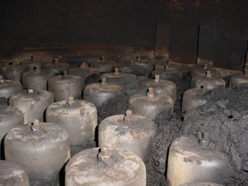
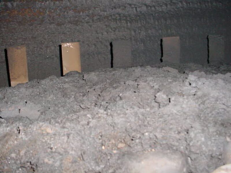
The towers were originally equipped with 12 single pass bubble cap trays. The trays were designed with a downcomer inlet sump in order to provide static liquid downcomer sealing and extend operating range. This design element was commonly done in low liquid rate applications. However, it should never be applied in “dirty” services as these pots can be filled with debris and potentially block liquid flow exiting the downcomers.
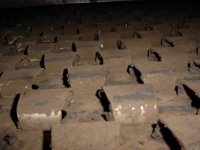
The feed gas was introduced into the tower via a flush nozzle. Hence, there was no vapor distributor. The bottom of the nozzle was only 4 in. above the HLL [high liquid level], which likely contributed to liquid re-entrainment from the bottom liquid surface to the bottom tray. The small clearance not only reduced capacity, it perpetuated foaming and fouling on the tray. Fouling was very severe as can be seen in Figs. 1 and 2 after only 1 year of operation.
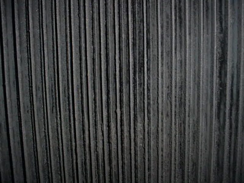
At the top, the tower was equipped with a vertically oriented (horizontal vapor flow) vane pack mist eliminator with two windows. It was a simple vane pack with 5/8-in. (16-mm) blade spacing with no pockets. The vanes drained via a downpipe behind the inlet weir of the first tray. The mist eliminator was undersized with a k-factor of 0.8 ft/sec at 240 MMscf/D. The gas outlet scrubber was also equipped with a similar vane pack. At the time, this scrubber was found to be sized also too small and some of the gas was being bypassed due to excessive pressure drop.
As illustrated in Fig. 3, some fouling can be seen in the vane pack, but the fouling was less severe than in the bottom of the tower.
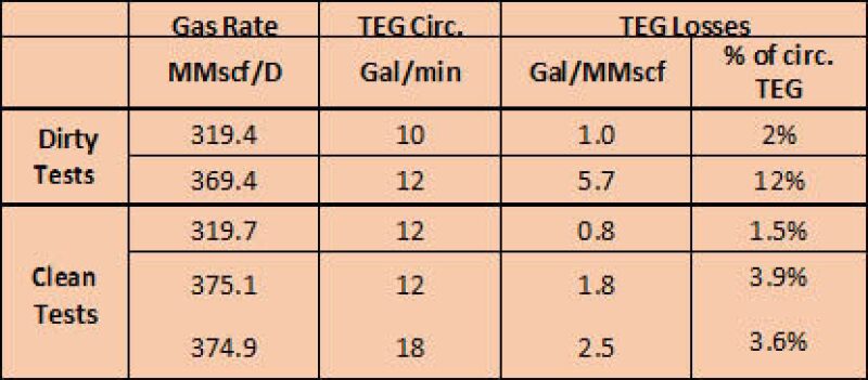
Although each tower was designed to process 240 MMscf/D, it could actually process around 280 MMscf/D when the tower was clean with TEG losses at around 0.6 gal/MMscf. Capacity would drop by 50% within 9–12 months with excessive pressure drop due to extreme fouling and foaming on the trays. The fouling was restricted mostly to the bottom of the vessel and the bottom three trays and decreased moving up the column. Foaming was clearly visible in the level bridles, causing low-level control trips and upsets throughout the system. Gamma scans also verified foaming in the bottom section of the tower. Fouling also restricted the TEG circulation rate.
Debottlenecking to 750 MMscf/D
Future operations required the total throughput at the Wyoming facilities to increase to 375 MMscf/D per process train. Also, annually planned shutdowns were to be eliminated. Reduction in TEG carry-over was also desired as the TEG would have to be recovered downstream at the Shute Creek Facility before entering the gas treating units. The recovered TEG is processed and trucked back to the Black Canyon Facility.
The following modifications were performed in Process Train 1, August 2001.
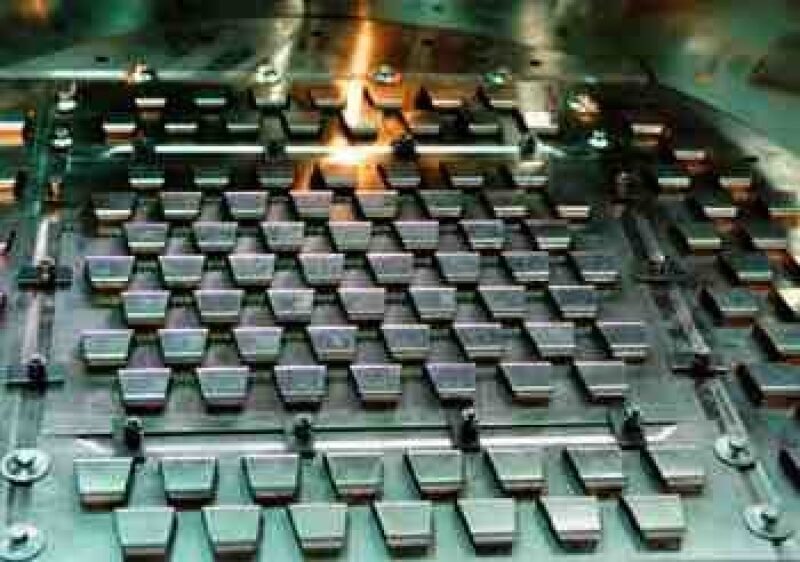
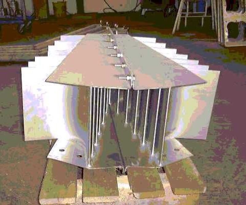
- Replaced all bubble caps with Provalve fixed valves (no movable caps). The orifice opening is similar to a moving valve, but the fixed cap pushes the vapor out more horizontally, reducing the accumulation of fouling material on the tray deck (Fig. 4). Structured packing was not considered due to the heavy fouling service.
- Removed all downcomer inlet sumps.
- Removed bottom seal pan and extended the downcomer from the bottom tray to the bottom liquid level to avoid trapping fouling material in the seal pan.
- Installed Koch-Glitsch Inlet Vane Diffuser at the gas inlet nozzle (Fig. 5).
- Note: No modification work was performed on the vane pack mist eliminator at the top of the tower.
The tower operated for an entire year at 375 MMscf/D with lower pressure drop and equivalent water removal and circulation rate. Liquid level at the bottom of the tower was fairly steady. The tower was pushed to 400 MMscf/D for about 6 hours and plant stability was maintained with no visible hydraulic limitations. However, the TEG carry-over was high at 5.7 gal/MMscf at 375 MMscf/D. Due to the very low circulation rate and high gas velocities, the trays were operating in the spray regime and therefore the existing vane pack was being overwhelmed with liquid and small droplets due to some foaming. The k-factor through the vane mist eliminator was at 1.17 ft/sec.
The tower was opened in the summer of 2002 and as can be seen in Fig. 6, the amount of fouling on the Provalve was considerably less than with bubble caps, even though it was operating at 34% higher gas rates. Fouling material was present throughout the trays, but most of the vapor passages through the valves were not blocked.
The bottom of the tower (sump) was now “dirtier” with more solids. The inlet vane diffuser also collected some solid material with most of the solids observed at the end of the distributor with about one-quarter to one-third of the vanes blocked.
Cleaning the Provalve was much easier because this task could be done in situ; instead of removing all of the bubble caps because of heavy fouling on the inside of the caps.
During this turnaround in the summer of 2002, the same modification was done in the TEG contactor in Process 2. There was one exception: the inlet vane diffuser had fewer vanes; in other words, larger vane spacing. This change was made to reduce the amount of fouling material collected in the vane and facilitate cleaning.
The Carry-Over
The TEG carry-over into the Shute Creek facility was higher than expected and added considerable operating cost to its recovery. The high entrainment rate was attributed to two main sources:
- The “dirty” system contaminated the TEG causing a higher degree of foaming and small droplets were now being entrained in greater amounts due to the high superficial vapor velocity at 375 MMscf/D.
- The mist eliminators vane packs were too small for high gas rates and were not able to remove the entrained liquid. The downstream knockout drum was not collecting any liquids and was being entirely bypassed.
During the turnaround in 2002, a Calgon carbon bed filtering system was installed to treat the entire TEG circulation rate in Process 1. This allowed a direct comparison between a “dirty” system prior to the turnaround and a comparison with Process 2, which had no carbon filtration. The carbon filtration had a significant impact on the entire operation of the TEG system: better stability, less to no foaming, and higher circulation rate. The entrainment rate dropped from 5.7 gal/MMscf to 1.8 gal/MMscf. For further reading regarding the implementation and testing of the carbon filtration system see MacFarland et al.
In the meantime, Process 2 was already seeing increased carry-over and overall system instability only 2 months after the shutdown. Foaming could be seen in the level bridles. To be fair, Process 2 has always performed worse than Process 1 as the gas is fed first to Process 1 off the manifold. This gas is cleaner as most of the solids will continue down the line to Process 2.
Although adding the carbon filtration on the TEG was a huge improvement, the carry-over was still unacceptable especially when the TEG circulation rate was increased to 18 gal/min. The carry-over increased further as the flow rates were pushed beyond 375 MMscf/D to 400–425 MMscf/D.
It was decided to replace the existing top mist eliminator vane pack with demisting cyclones at the next opportunity in Process 1 and Process 2 in May and October of 2003.
Demisting Cyclones
ExxonMobil had successful experience with demisting cyclones at high pressure in a hydrocarbon service. However, this application would be a first time application of demisting cyclones in a TEG service. The high CO2 concentration in the feed gas also made it a special application because the conditions were outside the range of available vendor data. Nonetheless, TEG losses were expected to be less than 1.0 gal/MMscf after installation.
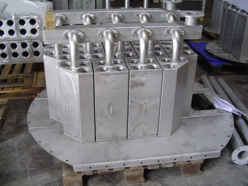
After discussions with the vendor CDS (now FMC Technologies), the number of cyclones and mechanical implementation of the cyclones were agreed (Fig. 7).
The demisting cyclone deck was able to be installed without any welding to the vessel shell by modifying the existing vane pack internal support structure. The inlet weir on the top deck was also modified to provide sufficient head to seal the cyclone drainage pipes.
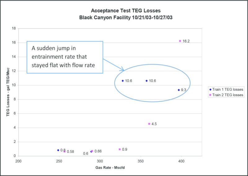
Upon startup, the performance of the demisting cyclones was similar to the vane packs at low gas throughputs of 240–280 MMscf/D. However, as flow rates increased, performance deteriorated for both contactors to an unacceptable level.
As can be seen in Fig. 8, Process 1 TEG losses climbed rapidly from 0.6 to 10.6 gal/MMscf between 290 MMscf/D and 328 MMscf/D, only a 13% increase in flow. The carry-over stayed relatively flat with increased gas flow rate. In the meantime, the TEG carry-over in Process 2 was less than in Process 1 and followed a more familiar parabolic function typically associated with re-entrainment. Historically, Process 1 always performed slightly better than Process 2, as the latter receives more solids. So, two different phenomena were possibly being faced.
In addition, the observed pressure drop for both units was about 15–20% higher than calculated, with Process 2 operating with a slightly lower pressure drop.
A number of theories were developed.
- The new trays with increased flow rate were operating in the “blowing regime”. Essentially all liquid is being entrained, leaving the tray decks dry. Provisions were made to minimize this event from occurring by blocking the outlet weir with pickets and providing sufficient hole area. This operating regime is also more likely to occur at lower circulation rate. For all the performance tests, the circulation rate was increased to 18 gal/min. In terms of mass transfer performance, the tower was performing as expected with acceptable gas dewpoint. Therefore, this scenario was not very likely.
- The trays were operating in a spray regime such that a significant amount of liquid was being entrained and overwhelming the cyclones. High entrained liquid rate could explain the high pressure drop.
- Foaming on the trays will have similar consequences as point 2 above. These towers have a history of foaming, but after the carbon bed filtration was added, the TEG had a smaller tendency to foam. In addition, cyclones should be able to break foam much better than the vane packs.
- High-viscosity liquid and high vapor density were causing film instability in the cyclone resulting in surface re-entrainment.
- Insufficient drainage head. Due to the unexpected high liquid load to the cyclones, the required drainage head was too high and the cyclones were unable to drain properly.
- Syphoning. The high pressure drop was causing some liquid to be siphoned from the tray below.
- Downpipes for drainage were not sealed properly and vapor was bypassing. This can occur with leakage on the tray deck or around the inlet weir.
Looking at Fig. 8, there was something unusual about Process 1. The quick jump in entrainment rate within a relatively small increase in gas rate is an indication of either liquid syphoning or gas bypass through the downpipes. With gas bypass, we would also expect a decrease in pressure drop, which was not the case during this series of tests.
First Fix Attempt
Based on the high pressure drop and the quick spike in entrainment rate in train 1, the lead hypothesis was that the available head was not sufficient for drainage. In November 2003, the Process 1 contactor was inspected and no mechanical damage was found.
No fouling was found on the tray, in the cyclones, or in the cyclone drain header. It was noticed, however, that the inlet weir was not properly sealed against the vessel wall. Dark discoloration on the vessel wall also suggested that some liquid was bypassing the inlet weir. It was unclear if the amount of leakage was significant enough to lose seal around the downpipes.
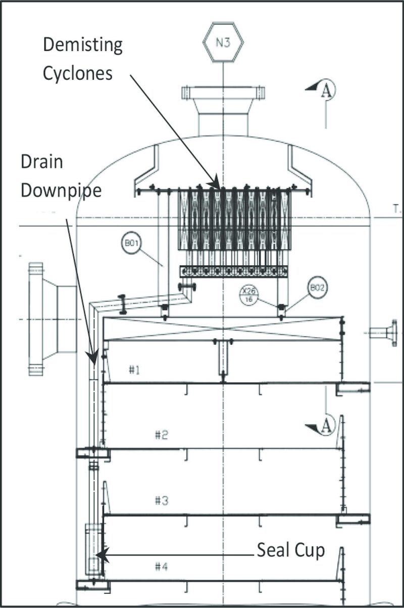
During this downtime, the sealing of the downpipes were moved from behind the inlet weir of tray 1 to the downcomer of tray 4 as shown in Fig. 9. To make sure that sufficient liquid height existed to seal the downpipes, a seal cup was added to assure sufficient static seal. Special modifications were required to allow the downpipes to pass through the downcomer floor of tray 2. Seal plates were seal welded around the downpipes and downcomer floor to prevent leakage. Downcomer capacity was also checked to make sure that the additional space being taken up by the seal cup and downpipes would not control capacity of the tower. The outlet weir on tray 3 was modified to make certain that liquid would fall into the seal cup. Prior to startup, the seal cup was filled with TEG.
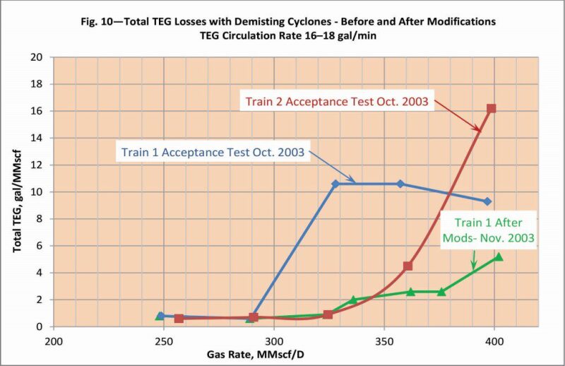
As can be seen in Fig. 10, the measured TEG losses were significantly reduced after the modifications were made to the Process 1 TEG contactor; however, these losses were still not acceptable. The process guarantees and the expected cyclone performance was less than 1.0 gal/MMscf.
After a re-evaluation of the new data, there were two leading causes for the high entrainment:
- Insufficient number of cyclones for this particular system (high viscosity and high vapor density) causing film instability and re-entrainment.
- Liquid flux rate hitting the cyclones from the trays is too large at the higher gas rates. The high pressure drop is an indicator that the cyclones are seeing a larger liquid load than the original design assumptions.
The next scheduled turnaround was to be in September 2004, when a final fix would be attempted in Process 1 first.
Second Fix Attempt
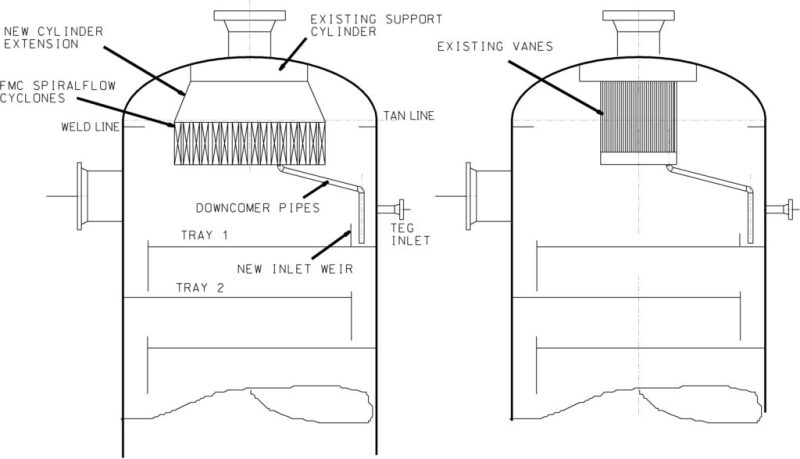
Not knowing which of the two causes was controlling, it was decided to fix everything. More cyclones were added to reduce the momentum and at the same time decrease the liquid load per cyclone (Fig. 11). This also reduced overall pressure drop and drainage head requirement. In addition, a new vane pack system was installed, covering the entire bubbling area, about 15 in. above the tray deck, to knock down bulk liquid (Fig. 12). This reduced the liquid load to the cyclones. The vanes have no pockets due to the known fouling associated with this application.
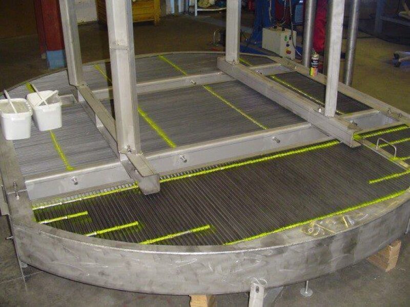
CDS (FMC Technologies) developed a clever design to integrate the vane pack into the tower with limited space. Since the vane pack occupies the entire bubbling area, it blocked the top vessel manway. The vendor developed a support system in which the vanes fitted into C-channels such that the vanes could easily be pulled out through the manway to allow access to the top tray. The vane support structure was fixed to the internal attachments supporting the demisting cyclones. Thus, no welding was required.
In October 2004, a performance test was done on the modifications. The TEG loses decreased from about 6 gal/MMscf to 0.21 gal/MMscf at 375 MMscf/D. To date the TEG losses are less than 0.6 gal/MMscf at rates greater than 375 MMscf/D.
Conclusions
As was demonstrated, a clean TEG system will minimize foaming and increase capacity as well as decrease maintenance, operating expense, and downtime.
Although vendor data were available on demisting cyclones with glycol at elevated pressure and good experience was also available with cyclones in hydrocarbon service at high pressure, this application was outside the data range. The entrained liquid load is also an important parameter that often is ignored or unknown, as was the case at the LaBarge Facility.
Although it took 18 months to troubleshoot and two separate vessel entries after the cyclones were initially installed, the gas capacity of the Black Canyon Facility has almost doubled. The operators and facility engineers at Black Canyon Facility were extremely cooperative and patient with the efforts. The vendor, FMC Technologies, was also extremely cooperative and followed through until the problem was fixed.
Authors and Acknowledgements
Thanks to current and past Separations Technology Technical Section officers and directors for their contributions. A list of current members can be found here. Past members include Chris Buckingham and Robert Chin. Chin serves as the primary contact and informal editor for the series. Send your ideas and topics of interest for separations articles to him at r.w.chin@att.net.
References
- Polderman, H. et.al. Experience with Debottlenecking of Gas Dehydration Plants, Laurance Reid Gas Conditioning Conference, February 2006.
- MacFarland, S. et.al. Sour Gas TEG Dehydration: Water Content Prediction, Wet Gas Sampling Technique, Solvent Contamination and Contactor Performance, Laurance Reid Gas Conditioning Conference, February 2003.
- Yang, M. and Kollinger, S. 2016. The Evolution of Glycol Contactors, Sulzer Technical Review.
Ed Grave is upstream senior technical advisor for fractionation and separation at ExxonMobil Upstream Research Company in Spring, Texas. Recognized in the company for his expertise in advancing new technology, he led ExxonMobil’s effort to design and qualify a separation system for ultradeepwater. Grave initiated and is the technical chairman of the joint industry Separations Technology Research Program on qualifying separation equipment. He also served as vice chair of SPE’s Separations Technology Technical Section. Grave graduated from New Jersey Institute of Technology with an MS degree in 1982. He began his career at Lummus and joined Mobil Research & Development Company as a mass transfer specialist in 1990.
Norman Yeh is the fractionation and separation team lead at ExxonMobil Upstream Research Company in Spring, Texas. He graduated with his bachelor’s and master’s degrees from the Massachusetts Institute of Technology and his PhD from the University of Texas at Austin, all in chemical engineering. Since joining ExxonMobil in 2002, he has supported both capital projects and operating facilities with process equipment design and troubleshooting. In his current role, Norman is focused on research and development, qualification, and applications for compact mass transfer and separation technologies. He also serves as a director for the SPE Separations Technology Technical Section and as a member of the Design Practices Committee for Fractionation Research Inc.
is a senior process engineer and fractionation/separation specialist at ExxonMobil Upstream Research Company in Spring, TX. He graduated with his bachelor’s in chemical engineering from Universidad Politecnica Antonio Jose de Sucre in Barquisimeto, Venezuela, in 1998 and his master’s degree in gas engineering from Universidad del Zulia in Maracaibo, Venezuela, in 2006. He has more than 15 years of experience in the oil and gas industry, mainly as a process engineer supporting production and operations of oil and gas facilities. He joined ExxonMobil Venezuela in 2006 and has provided facilities and process engineering support for new projects as well as facilities commissioning and startup. His current role includes research, design, and troubleshooting for all fractionating and separation systems for ExxonMobil’s upstream activities worldwide.