
Oil droplet coalescence is a critical process for the efficient cleaning of produced water. Coalescence is a complex process which is dependent upon mechanistic events (droplet collisions) and the physical-chemical properties of the oil and water. These fluid properties include the ability of droplets to approach one another closely during a “collision event,” the ability of droplets to deform during a collision, and the ability of films or any other stabilizing entities on the surface of the droplets to drain or move away from the droplet collision area so that the colliding droplets can merge into a single droplet. Although equations describing many of the key properties that control coalescence have been developed by a number of investigators, the reliable quantitative modeling of oil droplet coalescence rates remains a complex challenge. However, by understanding the factors involved in oil droplet coalescence, the Savvy Separator engineer can assess which operational or chemical factors in the treatment system are affecting droplet growth and make judgments as to how those factors can be manipulated to enhance coalescence rates.
Introduction
Most of produced water treatment is dependent on the parameters that are embodied within Stokes’ Law. These parameters are the density differential between the oil and the water, the viscosity of the continuous (water) phase, and the diameter of the oil droplets to be separated. Because the rise velocity of an oil droplet is dependent upon the square of the droplet diameter, droplet size is critical to the clarification of oily water in vessels and tanks. More often than not, as-received oil droplet sizes are too small for efficient separation to take place within the time available in a particular piece of process equipment. Oil droplet size growth through coalescence is the process that allows water clarification to take place within a reasonable time period in equipment which is reasonably sized.
Oil droplet coalescence is a complex process which is dependent upon several factors, including
- Number of droplet/droplet collisions
- Relative velocity at which the droplet collisions take place
- Size of the droplets which are colliding
- The electrical charges surrounding the oil droplets (their zeta potential)
- The oil/water interfacial tension
- Thickness and stability of the film on the surface of the oil droplets
Viscoelastic properties of the stabilizing film on the surface of the oil droplets
- Interfacial film mobility
- Interfacial film elasticity
- Interfacial film viscosity
- Interfacial film mobility
The objective of this article is to provide an overview of the key parameters that govern the process of oil droplet coalescence and an understanding as to how the Savvy Separator engineer can adjust parameters within a water treatment system to enhance coalescence.
Three-Step Process of Coalescence
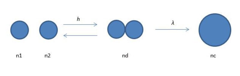
The process of coalescence can be envisioned to occur in three steps, as shown in Fig. 1 (Narsimhan 2004):
- Two droplets approach to within a distance of 10 to 100 microns. At this distance the approaching faces of the droplets deform and a disk-shaped film forms between the droplets. Film drainage begins and the surface forces (electrostatic repulsive and van der Waals attraction) become significant.
- The liquid film between the droplets drains down to a critical thickness of 0.01 to 0.1 micron.
- The thin liquid film ruptures and results in droplet coalescence.
Any of the three steps can become the rate-limiting step for coalescence. By considering coalescence as a three-step process, it is easy to understand how factors such as droplet collision rates, oil droplet size, oil/water interfacial tension, and oil droplet film properties affect droplet size growth.
Droplet Collision Rates
The obvious first step in the coalescence process is that two oil droplets must collide. The rate of collisions between dispersed droplets is primarily controlled by the concentration of oil droplets (number per unit volume), the size of the droplets, and by their relative motion due to turbulent velocity fluctuations in the water phase. The dependence of droplet collision rates on their concentration is intuitively obvious.
It is also clear that smaller droplets will tend to collide less frequently due to their smaller cross-sectional area. But size also makes a difference in the efficiency with which colliding droplets will coalesce. The larger the oil droplets, the more momentum they will have and the more energy exchange that can take place during a collision. Because smaller droplets have less mass and exchange less energy in a collision, any net electrical charge on the surface of an oil droplet becomes more important for inhibiting coalescence of smaller droplets during a collision. Another factor that slows coalescence rates for smaller oil droplets is the fact that they are more rigid and deform less due to the internal pressure that develops from the oil/water interfacial tension. This internal pressure is referred to as the Laplace pressure and is defined by the Young-Laplace equation:
∆P = 2σ/R
where:
σ = Oil/water interfacial tension
R = Radius of the droplet
As mentioned above, droplet collision rates are also influenced by the relative velocity fluctuations of the tiny turbulent eddies which are present in the water. In produced water systems the typical range of dispersed droplet size is 1–100 microns. The small droplets are comparable to the Kolmogorov length scale for small turbulent eddies (20 to 25 microns) in the water phase (Vankova and Tcholakova et al. 2007). On the basis of the turbulent length scales for flow fields in water treatment equipment, the relative motion and thus the collision of dispersed droplets having the typical size of 1-100 microns is mostly due to these turbulent eddy velocity fluctuations. The mean velocity gradients of the flowing fluid in a pipe or vessel are generally small by comparison and not significant. However, this statement may not apply to very high-velocity gradients experienced across valves, pumps, static mixers, or some vessel/tank internals.
Although collision effectiveness for coalescence can be enhanced by the introduction of mild, low-shear turbulence, field experience indicates that the use of static mixers in a pipe carrying produced water are counterproductive because the mixers tend toward relatively intense eddies that can shear oil droplets into a smaller size distribution rather than enhancing their coalescence.
Zeta Potential and Aqueous Surface Films Impact the Coalescence Process
For droplets to coalesce, they must approach each other very closely. There are several significant barriers to such a close approach. The first barrier is the viscosity of the water phase that must move out of the way as the droplets approach their collision point. Anything that increases the viscosity of the water phase will slow the displacement of water from between the colliding droplets and inhibit their coalescence. The presence of a water-soluble polymer, the presence of a high dissolved salt content, and the presence of colloidal solids are examples of materials which can increase the viscosity of water and thus impede droplet coalescence. Increasing the water temperature is an example of how to reduce the viscosity of water and increase the efficiency of coalescence for colliding droplets. Since the viscosity of low-TDS water declines from 1.0 cP at 70oF to 0.5 cP at 130oF, it is not surprising that oil droplet coalescence rates are enhanced at elevated temperatures.
Another major barrier to the close approach of oil droplets during a collision is the presence of a charge cloud—referred to as the electrical double layer—around each droplet. The measureable strength of this double layer is referred to as the zeta potential for the droplet, illustrated in Fig. 2. Since the colliding oil droplets will have the same surface charge, a repulsive force develops between the droplets during a collision event and the coalescence of oil droplets is inhibited. The size and the strength of the double layer become greater as the salinity of the water decreases. At higher salinities, the increased conductivity of the water disperses the charge cloud and collapses any residual charge to regions very close to the oil droplet surface. The stability of small droplets in water from gas-condensate fields is in part explained by the presence of a significant oil droplet zeta potential in the low-TDS water.
As can be seen in Fig. 2, the second layer of charges surrounding a particle is known as the diffuse layer or the “Stern Layer.” It is composed of ions drawn to the surface charge via electrostatic attraction. The second layer is more loosely associated with the object than the surface charge, because it is made of free ions that move in the fluid under the influence of electrostatic interactions, thermal motion, and fluid shear, rather than being firmly adherent to the surface. The net electric charge of the diffuse layer is equal in magnitude to the net surface charge, but has the opposite polarity. As a result the complete structure is nearly—but not quite—electrically neutral. The residual charge imbalance is the previously discussed quantity known as the zeta potential. Zeta potential measurement instrumentation is commercially available and in fairly wide use in research and specialized commercial laboratories.
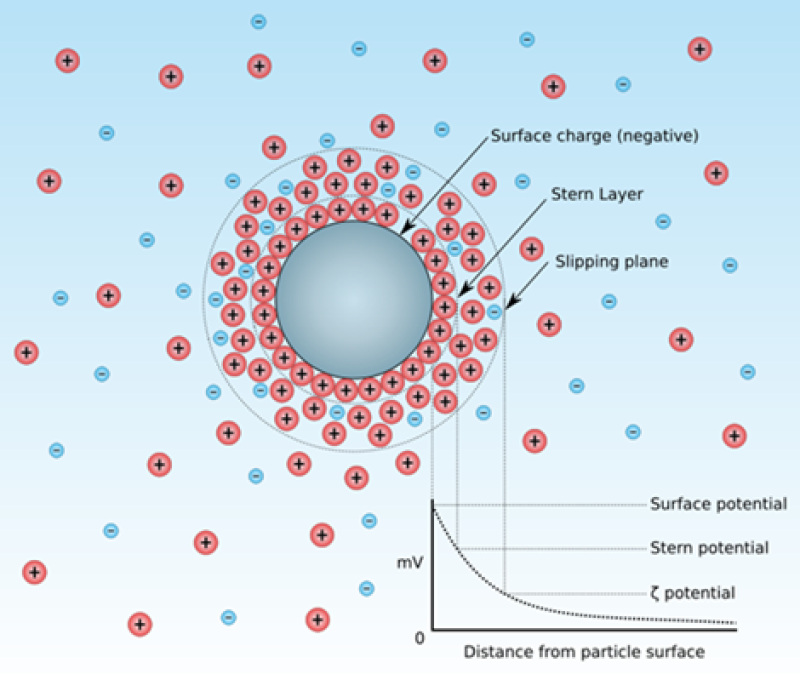
The coalescence-inhibiting effect of the electrical double layer can be overcome by both mechanical and chemical means. Mechanically, if the colliding velocity of the oil droplets is increased by, for example, the introduction of mild turbulence, then droplet-droplet collisions will be more energetic and the close approach required for coalescence becomes more likely. Chemically, if the surface charge on the oil droplets is reduced or eliminated by the introduction of a chemical with an opposite charge, then the affect that the double layer (zeta potential) has on the development of repulsive forces between oil droplets is likewise reduced or eliminated. In the case illustrated in Fig. 2, the introduction of an anionic (negatively charged) polymer can be used to neutralize the electric double layer.
Oil/Water Interfacial Tension
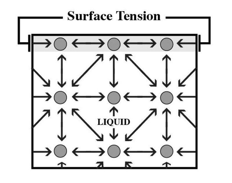
Another barrier to the coalescence of colliding oil droplets is the surface film present on the oil droplet. In a “clean system” without the significant presence of chemicals or other entities, the oil droplet will develop a surface tension as illustrated in Fig. 3. Surface tension is a stress acting parallel to the surface of the oil droplet. When an oil droplet is immersed in water, this surface tension is referred to as the oil/water interfacial tension—a quantity that is relatively simple to measure in a benchtop laboratory test. Note that the liquid/liquid interfacial tension is not the process-simulator-reported surface tension property for a simulated stream; the process simulator reports the calculated gas/liquid surface tension only. Surface, or interfacial tension, is a consequence of the intermolecular forces and the way that molecules pack together at an interface. This is further illustrated in Fig. 3, which shows that in the bulk fluid, the molecules are subject to interactions on all sides. However, near the surface, the interactive forces are only present from one side, thus allowing a net attractive force to develop at the surface of the liquid.
In the absence of surface active chemicals, the interfacial tension between oil and water phases is about 42 dynes/cm. However, if there are surfactants present (either naturally occurring or artificially introduced), then the surface tension can drop dramatically. In a quiescent environment such as inside a tank or a vessel, the rate of oil droplet coalescence will increase as the interfacial tension declines. An oil/water interfacial tension between 5 and 10 dynes/cm, for example, would be a beneficial environment for oil droplet coalescence. However, a low value for the interfacial tension for oil and water that is subjected to high shear forces, for example, across a control valve or through a static mixer, will tend to result in the formation of smaller oil droplets, which are, as discussed above, more difficult to coalesce. Anytime the oil/water interfacial tension drops below 3–5 dynes/cm, one can expect that smaller oil droplets will be generated upstream of water treatment equipment, and the rate of oil droplet coalescence will be slowed overall.
Film Drainage
The magnitude of the oil/water interfacial tension is one factor that impacts the ability of oil droplets to coalesce. Another factor is the presence of a stabilizing film on the surface of the oil droplet that can reduce the effectiveness of coalescent collisions. The stabilizing film can be oily, aqueous, chemical, or solid in character. For example, the presence of excess surfactant on the surface of an oil droplet will contribute to the formation of a stable water film covering of the water droplet, which is held in place by the hydrophilic end of the surfactant molecule.
As two droplets approach each other, the pressure in the fluid between the droplets builds up slightly and there is a tendency for the leading edge of each droplet to flatten. This creates a disk-shaped film of fluid between the droplets. The extent of flattening depends on how rigid the interface is. If the oil in the droplet is viscous, then the droplet will not flatten so readily, and the radius of the film disk will be smaller. If the interface is readily deformed, the film disk radius will be large. The situation is illustrated in Fig. 4.
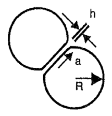
For coalescence to take place, anything between the colliding deformed droplets that stabilizes the interfacial film must be moved aside—including any residual water film or solid contaminants.
Consider that the larger the deformation of the droplets, the larger the radius of the disk-shaped film will be. A large film radius will increase the film drainage time and reduce the probability of coalescence during a collision event. Since larger droplets will also form larger film disks, larger droplets require a greater time of interaction for film drainage (and thus coalescence) to take place. Contaminants such as waxes, asphaltenes, surface active chemicals, or particulate solids (clays, iron sulfides, asphaltenes, scale mineral precipitates, etc.) can retard both the droplet deformation and the drainage of the interfacial film.
The phenomenon of droplet stabilization by solids adsorbed on their surface is known as “Pickering stabilization” (Ngai and Bon 2014). It is interesting to note that not only do the solids on the surface of a droplet have a mechanical impact on the inhibition of droplet coalescence as described above, they also have a thermodynamic stabilizing impact on the oil droplet surface by reducing the droplet’s surface energy. This thermodynamic stabilization explains why solids-stabilized emulsions in the oil field can often be so difficult to resolve
Chemical Impacts on Oil Droplet Coalescence
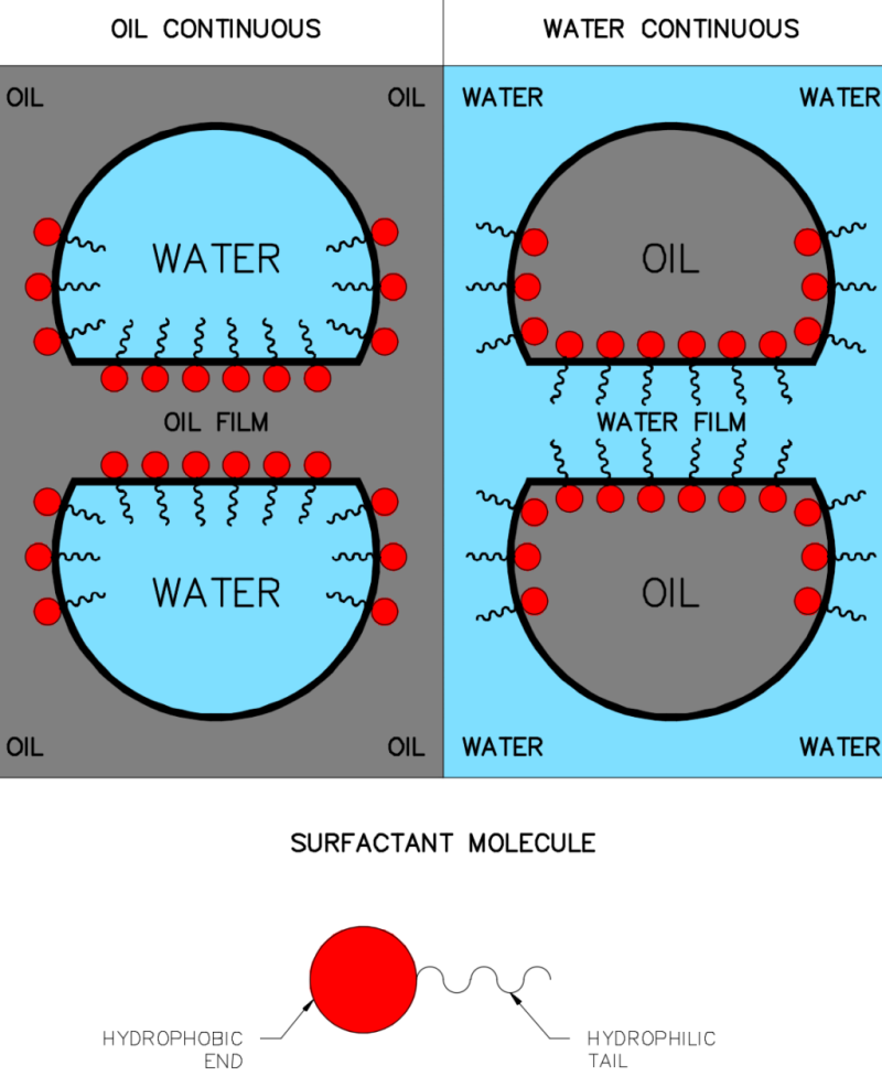
Given the above considerations, one begins to understand how and why some commonly used chemicals can negatively impact water treatment by their ability to stabilize oil droplet films. Demulsifiers, for example, act by taking up residence at an oil/water interface and allowing water droplets in the oil phase to coalesce (Fig. 5). Note in the figure that the hydrophilic tails of the surfactant that stick out into the water around the droplet provide a means for stabilizing an aqueous film that can be a formidable barrier to droplet coalescence. This mechanism explains why some chemicals that act as very efficient water clarifiers and coalescence enhancers can instead act as oil-in-water emulsion stabilizers if overtreatment takes place.
One precaution the Savvy Separator engineer can take is to ensure that chemical injection rates always match water flow rates. One approach to this objective is to use automated control of chemical injection rates by varying chemical injection rates based on a flow transmitter signal. Field experience has shown that such controls can be effective at enhancing the performance of a water treatment system while decreasing the total volume of chemical that needs to be injected—especially when slug flow is an endemic feature of the production.
One common source of unwanted chemicals is recycle streams within a treatment facility. Skim fluids from a flotation unit are often contaminated with emulsion-stabilizing polymers or other flocculent chemicals. The rejects from an oil/water hydrocyclone are often laden with excessive fine solids which, when returned to the front-end of a process train, can form solids-stabilized interface emulsions that degrade both water quality and oil dehydration.
For demulsifiers, using the correct treating rate will destabilize water droplets dispersed in oil and enhance their rates of coalescence. But overtreatment with a demulsifier can result in the formation of a stable aqueous interfacial film on the surface of oil droplets that results in the formation of an intractable emulsion (Yang, Galbrun, and Frankiewicz 2004).
A corrosion inhibitor chemical usually includes multiple components. One component is the inhibitor itself, typically a film-forming amine that can reside at the oil/water interface, stabilize the interface, and inhibit droplet coalescence. Another component is a surfactant, which is included in the corrosion inhibitor formulation, to improve the ability of the inhibitor to penetrate an oil film on the surface of the pipe, tank, or vessel wall. Unfortunately, the surfactant will also reduce the oil/water interfacial tension and contribute to the formation of smaller, more stable oil droplet dispersions during upstream operations such as through pressure drops across flow control or level control valves. It is not unusual to find that the surfactant in a corrosion inhibitor formulation is an important contributor to a decline in the performance of a water treatment process.
Asphaltenes, even stable asphaltenes, and their accompanying resins can have an impact on the coalescence process by their control of the physical/chemical properties of the oil/water interface. Being highly aromatic and somewhat polar, asphaltenes have an ability to become concentrated at a droplet’s oil/water interface. In doing so, they impact several important properties of the interface and effect a Pickering stabilization of oil droplets.
One commonly used means to enhance the ability of a surfactant to reduce the oil/water interfacial tension and stabilize an emulsion is to add an alcohol as a “co-surfactant.” In cold environments or in deepwater offshore production, methanol is often utilized to suppress hydrate formation. The combination of methanol and a surfactant from any other source can result in very low interfacial tensions and the formation of very small oil droplets whose subsequent coalescence to a separable size is also inhibited.
Mobility and Deformability of the Interface
During the collision process, fluid motion in the droplets and fluid motion in the interfacial film must be considered. During a collision, oil droplets experience forces that push against and shear the oil/water interfaces. As the interfacial film drains from between the droplets, it will apply a shear force on the interface in the direction of liquid flow. If the interface is mobile, then the film will flow and this flow will create an internal circulation within each droplet. Flow of the interface and internal circulation reduce the drag forces that inhibit liquid drainage. This increases the drainage rate and shortens the interaction time required for droplets to successfully coalesce. Unfortunately, small oil droplets do not benefit from this interfacial mobility since their elevated Laplace pressure tends to limit the internal fluid circulation and, as a consequence, stabilizes the oil droplet against coalescence.
Presence of Surfactants and Particles at the Interface
Some surfactants, fine particulate solids, and film-forming agents, whether naturally occurring in the oil and water, or added, for example, as corrosion or hydrate inhibitors, can have a dramatic effect on coalescence. Both film-forming agents and particles tend to reduce the drainage rate of fluids from between the colliding droplets. Surfactants may either increase or decrease the drainage rate depending upon their character and the impact they have on, for example, interfacial viscosity. Also, at a close enough distance, the presence of contaminants at the interface can contribute to the development of a repulsive force between the two droplets by affecting the zeta potential of the droplets. This is another effect which reduces the probability of coalescence.
The Gibbs-Marangoni Effect
When droplets that have surfactants on their interface collide, the “Gibbs-Marangoni” effect leads to elasticity of the interface. As the droplets approach, the fluid in the film begins to drain. This drags surfactant off the flat interface, pushes it to the surrounding curved interface, and creates an interfacial tension gradient. The result is a lower concentration of surfactant on the flattened interface compared to the curved interface surrounding it. The change in interfacial tension with a change in interfacial area is referred to as Gibbs elasticity. As the name implies, this gives the interface an elastic-like quality, which stabilizes it against mechanical disturbances which might otherwise lead to film rupture Fournier and Cazabat 1992.
There are three physical/chemical parameters that contribute to the stability of the interfacial film between two colliding oil droplets. These are:
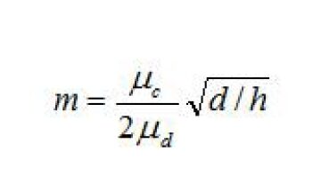
Mobility of clean interfaces. For oil/water mixtures that do not have significant concentrations of surface active material at the interface, a dimensionless mobility number can be used to characterize the drainage time. Davis et al. (1989) defined the interface mobility factor as:
where:
m = mobility number
d = diameter of the droplet (m)
μc = viscosity of the continuous phase (kg/m3)
μd = viscosity of the dispersed phase (kg/m3)
h = gap distance between droplets—film thickness (m)
The mobility number is based on the ratio of bulk phase viscosities. When m is large, the interface is mobile and flows in the direction of the film drainage. When m is small, the interface does not flow as much, and instead it imposes a drag on the film drainage process. Eq. 1 does not account for interfacial film elasticity or interfacial viscosity. When the interface is devoid of surface active materials, it acts like a liquid (i.e., it flows and allows rapid film drainage). But when a surface contaminant is present (e.g., asphaltenes, waxes, surfactants, polymers, or some solids), then film mobility declines—as do coalescence rates.
It is important to note that mobile interfaces have shorter film drainage times. If the oil in the droplet is viscous, then the drop will not readily deform. If the oil/water interface has a high concentration of surfactant, then it can become somewhat rigid and, again, oil droplet coalescence is decreased.
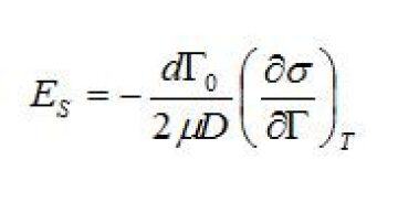
Gibbs-Marangoni elasticity and elasticity number. The elasticity number is a parameter that can be used to correlate the magnitude of the Gibbs-Marangoni effect on the rate of film drainage. In studies of different surfactants, crude oil constituents, and demulsifiers, the elasticity number is often used (Malhotra and Wasan 1988; Breen and Wasan et al. 1996).
where:
ES = elasticity number (dimensionless)
d = diameter of the droplet (m)
μ = viscosity of the continuous phase (kg/m3)
σ = interfacial tension (N/m)
\({\Gamma}\)0 = equilibrium concentration of surfactant at the interface (mol/m2)
D = diffusion coefficient of surfactant in the bulk water (mol/m/sec)
For almost all solutions the surface, or interfacial tension, decreases as the concentration of surfactant increases. Thus, the negative sign in the equation multiplied by the derivative of the interfacial tension gives a positive number. As the magnitude of Es increases, the coalescence rate decreases. Higher values of Es correspond to a more elastic and less fluid-like interface. Increasing the concentration surfactant at the interface, increasing the droplet diameter, and decreasing the decline in interfacial tension as a function of the concentration of surfactant all work to slow coalescence.
Interfacial viscosity number. The interfacial viscosity number is a measure of the interfacial film’s shear viscosity. In other words, it measures the extent to which the interfacial film itself resists flow. As previously discussed, the drainage of liquid from the disk imposes a stress on the interface that will cause it, and the fluid within the droplet, to flow. If the interface has a high resistance to flow, then it will flow slowly or not at all. The mobility of the interface is related to the interfacial viscosity number (Malhotra and Wasan 1988; Breen and Wasan et al. 1996). It is defined as:
where:
VS = interfacial viscosity number (dimensionless)
μc = viscosity of the continuous phase (kg/m3)
μs = interfacial shear viscosity (Pa m sec)\({\gamma}\)
d = diameter of the droplet (m)
Summary and Conclusions
The coalescence of oil droplets dispersed in water is a key component of any water clarification process.
Without efficient coalescence, the size and cost of water treatment equipment would increase substantially. The process of oil droplet coalescence involves droplet-droplet collisions, oil droplet deformation, interdroplet interfacial film drainage (both aqueous films and oily films), and finally the rupture of the stabilizing film so that multiple droplets can merge into a single larger droplet. Droplet collision rates are related to the concentration of droplets in the water, the size of the oil droplets, and droplet velocity distributions. The latter are primarily under the control of turbulent eddies in the water phase.
Factors such as the viscosity of the continuous water phase, the presence of charge barriers on the droplets, and the stabilization of aqueous or oily interfacial films by surface active chemicals and/or solids, both natural and injected, inhibit droplet coalescence. But the Savvy Separator engineer can overcome these inhibitions to coalescence by the use of mechanical or chemical means. Mechanically, heat and mild turbulence enhance coalescence while high shear or intense turbulence can inhibit coalescence by contributing to the formation of very small droplets.
Chemicals can be used to reduce or eliminate the charge barriers (zeta potential) that inhibit coalescence, or to reduce the stability of interfacial films. Overtreatment with one or more chemicals can have the opposite effect of stabilizing droplets and inhibiting coalescence. Recycle streams can be the unintended source of solids or chemical contaminants, which stabilize emulsions by inhibiting oil droplet coalescence.
Acknowledgement
Material for this article is based in part on the emulsions chapter to be included in an SPE book expected to be published later this year, “Produced Water.”
References
G. Narsimhan. 2004. Model for Drop Coalescence in a Locally Isotropic Turbulent Flow Field. Journal of Colloid and Interface Science, 272 (1): 197–209.
N. Vankova, S. Tcholakova, N.D. Denkov, I.B. Ivanov, V.D. Vulchev, and T. Danner. 2007. Emulsification in Turbulent Flow 1. Mean and Maximum Drop Diameters in Inertial and Viscous Regimes. Journal of Colloid and Interface Science, 312 (2): 363–380.
T. Ngai and S.A.F. (ed). 2014. The Phenomenon of Pickering Stabilization: A Basic Introduction. In Particle-Stabilized Emulsions and Colloids: Formation and Applications. Chapter 1, 1–7. Royal Society of Chemistry.
SPE 90409. 2004. Identification and Resolution of Water Treatment Performance Issues on the 135 D Platform by C. Yang and M. Galbrun, Schlumberger, and T. Frankiewicz, NATCO Group.
J.B. Fournier and A.M. Cazabat. 1992. Tears of Wine. Europhysics. Letters, 20 (6): 517.
R.H. Davis, J.A. Schonberg, J.M. Rallison. 1989. The Lubrication Force Between Two Viscous Drops. Physics of Fluids A: Fluid Dynamics 1 (1): 77–81.
A.K. Malhotra and D.T. Wasan. 1988. Interfacial Rheological Properties of Absorbed Surfactant Films With Applications to Emulsion and Foam Stability. In Thin Liquid Films: Fundamentals and Applications, ed. I.B. Ivanov, Chapter 12. New York, New York: Marcel Dekker Inc.
P.J. Breen, D.T. Wasan, Y.-H. Kim, A.D. Nikolov, and C.S. Shetty. 1996. Emulsions and Emulsion Stability. In Emulsions and Emulsion Stability, ed. J. Sjöblom, Chapter 4. New York, New York: Marcel Dekker Inc.

Ted Frankiewicz is engineering advisor at SPEC Services. He has more than 30 years' experience in oilfield process systems and produced water treatment, working in operations, equipment design and manufacturing, and process engineering. At SPEC he has designed equipment and process systems for and diagnosed performance issues with oil separation/dehydration and water treatment facilities internationally for major as well as independent operators. Previously, he has worked for Occidental Petroleum, Unocal Corp., and Natco Group. At Unocal, he was responsible for developing the water treatment systems that were installed in the Gulf of Thailand to remove mercury and arsenic and residual oil from produced water. He holds a PhD in physical chemistry from the University of Chicago, and 15 patents, and has authored more than 35 professional publications. Frankiewicz was an SPE Distinguished Lecturer in 2009–2010. He can be reached at tfrankiewicz@specservices.com

John Walsh is the director of R&D for CETCO Energy Services. He has nearly 30 years' experience in water treatment having worked for Shell for more than 20 years, and Westvaco Paper Co. prior to Shell. Until recently, Walsh was the president and managing director of the Produced Water Society. He has served on the SPE Board of Directors. He can be reached at john.walsh@mineralstech.com.