
The periodic calibration of vessel instrumentation is critical to ensure the ongoing performance and functionality of process vessels. Poor process vessel design is often exacerbated by miscalibrated instrumentation, leading to suboptimal operation and poor efficiency of the separator. In some cases, the location of the instrumentation can also lead to erroneous measurements. This article addresses how process flow conditions can lead to incorrect or misinterpreted level readings.
Introduction
The industry has expended considerable effort improving the design and configuration of separator and scrubber vessels. However, the selection and configuration of associated instrumentation has received little attention. Often instruments are configured for the initial operating conditions, but after that period has passed and operating parameters have changed, or additional contaminants have been introduced, the initial calibration is no longer appropriate and needs to change. Whilst holistic evaluation in the selection phase of level instrumentation should be comprehensive, it is essential that ongoing evaluation of the operating envelope is maintained through the life cycle of the process vessel and any changes translated into appropriate recalibration and as needed, reconfiguration of the associated instrumentation. Consequently, experience has shown that there are many more separator failures caused by incorrect data from instrumentation than from vessel internal configuration anomalies.
One of the key process control variables is liquid level. Common methods to measure levels include sight/level glass indicators and differential pressure (DP) sensors. Sight glasses, a direct level measurement, may come with options such as a magnetic follower and/or a level transmitter attached to a modified level glass. Level gauges using floats as the primary measurement sensor are also considered a direct means to measure the liquid level in process vessels. DP sensors are an indirect method where the level readings are based on the hydrostatic pressure exerted by the fluids, and accurate knowledge of the fluid densities are required.
The configuration of the above devices generally requires two flanged nozzle connections for each instrument, an upper and lower nozzle. To achieve the required measurement, the positioning of the nozzles is crucial. The design must ensure that the nozzles are always in contact with the appropriate fluid phase such as water and oil phases for the interface and the oil and vapor for bulk liquid level.
Fluid properties in actual operating conditions can be different from what was used for calibration, thereby resulting in erroneous level readings. In addition, the location of the level instrumentation can also lead to erroneous or misinterpreted level readings. This article provides some examples of lessons learned in troubleshooting instrument-related separator issues.
Fluid Properties
Most measurement techniques require calibration of the instrumentation using accurate and reliable properties for the fluids being measured. The physical specifications and conditions of the liquids in the vessels (emulsion, oil, and water) are crucial to the integrity and reliability of the measurement techniques applied. Hence, accurate assessment of the processed fluid specifications is important if calibration of the relevant instruments is to be done correctly so that accuracy is maximized and level reading deviations are minimized. Therefore, to avoid any deviation in level readings, reliable data must be obtained via regular representative sampling and analysis of the fluids being measured, including direct sampling from the vessel.
Changes over time. The nature of the process fluid is a mixture of oil, water, and gas. The process fluid can have different specific gravities at different stages within the process vessel; namely, entering the vessel as a fluid mixture or an emulsified fluid but leaving the vessel as distinctive phases. In addition, in many field applications, the process fluids come from different reservoirs, each with different properties. This will result in different density mixtures that will be processed through the separators. Consequently, the continuous variation in fluid properties will have an impact on the accuracy of the level measurements in the vessel. Although the error margin may not be significant enough to impact the safe operation of the vessel, it will have an impact on the separation efficiency and operability of the plant as a whole. Depending on the condition of the separation, variation in density of 5–15% can be the norm and the closer the instrumentation is to the inlet pipe, the higher the deviation, due to the nature of emulsions near the inlet of the vessel.
Similarly, level instrumentation will be affected as the water salinity changes. In the case of oil production, the water salinity changes due to various factors such as formation water variation or injected seawater breakthrough. In most fields the salinity variation can be less than 10–20%, but in some cases the variation can be as high as 50%, especially in gas condensate systems and pre-salt oil reservoir systems. These variations can have significant impact on the reliability of the level measurements; hence, updating fluid chemistry compositions (oil, condensate, and water) is essential to maintain the calibration of instrumentation.
Level instrument calibration data can also be enhanced by using the information obtained from process simulation models, as well as fluid analysis and live sampling. In theory, this is the best approach and is now used as a standard practice. However, to keep the instrumentation accurate over time, the fluid analysis data should be periodically updated to avoid potential errors that can result from changes in operating conditions, water cut, increase in gas/oil ratio, and change in fluid characteristics.
Note: Regular and appropriate maintenance are fundamental to achieving reliable instrumentation data. The standard and frequency of maintenance is largely dependent on the associated preventive and routine plant activities. In some cases, deviation from the planned activities should be rescheduled if operation deemed necessary.
Note: Apart from regular calibrations of the instrumentation using recent fluid properties, daily fluctuations in the process fluids can only be corrected using relevant algorithms or artificial intelligence tools to take into consideration operating fluctuations during the 24- hour period.
Note: Monitoring data and lab analyses of the produced fluid will help in the understanding of potential anomalies in the level readings due to oil emulsions in the production fluids.
a. Foam/Gas Carry-Under
Depending on the inlet devices and internals, experience has shown that gas carry-under and foaming at the inlet sections of separators (mainly in vertical gas condensate separator and scrubbers) can have a significant impact on the level reading and can result in poor control and performance. The reduced density of the liquid phase due to the gas content results in a false low liquid level which can lead to liquid carry-over in the gas phase and impact the downstream process compression units.
Although the gas carry-under and foaming issues have been experienced in both oil and gas/condensate systems, due to fluctuation in the condensate density caused by the dispersed and dissolved gas in the condensate phase during gas carry-under or gas blowby, the margin of error in the calibration of the instrument will be higher than for oil systems.
b. Water Content
Level instrumentation in many vertical scrubbers and separators can be difficult to calibrate correctly because of the presence of varying amounts of water and condensate within the liquid phase and in most cases, there is one common liquid outlet for both phases or the water outlet line is made redundant due to poor water separation. Hence there is a continuous fluctuation in the operating density. During operation, the bottom phase (water dominated) will be drained out leaving a higher condensate-containing layer on top, hence a different density fluid, which will result in varying level measurement as the ratio of liquid-layer heights change. These fluctuations can be critical in smaller vessels with the risk of losing optimum operating liquid levels and in many cases the liquid seal required to operate the downcomers (gas mist eliminator downcomers for draining liquid) correctly.
c. Pressure Variation
The liquid level is determined by measuring the difference in density of two fluids reaching equilibrium status within the separator. However, any internal pressure differences can result in changes in measured levels and consequently give different level indications due to pressure drop. As an example, a pressure change of 100 to 500 mbar (1.45 to 7.25 psi) between vessel compartments due to flooding of baffle plates or coalescing pads can lead to losing the uniform liquid level and consequently the interface level measurement within a separator, causing a level gradient; namely lower in the front end of the vessel below the setpoint and the correct level at the back end of the separator within the setpoint. Also, if there is some distance from the liquid level to the upper level-instrument nozzle, the resulting gas column can potentially cause further errors in the level measurement in the presence of foam.
d. Condensation
Regardless of the configuration of the process vessels, a common issue that can cause level measurement deviations is liquid condensation. When there is cooling in the instrument tubing and the vessel body, the drop in temperature may result in condensation of the gas creating liquid in the instrument tubing, which results in an offset of the level reading from the actual conditions in the vessel. This phenomenon is not unique to cold external environments, it has occurred in desert environments where the outside temperature falls below the process temperature during the nighttime.
Heat tracing of level instrumentation is a common way to prevent condensation; however, the setting for the temperature is critical because it can cause the very problem it is trying to solve. By setting the temperature too high, the more volatile components may be evaporated, resulting in an increased liquid density. Heat tracing can also be problematic from a maintenance perspective, as it is easily damaged. A cheaper option is lagging (insulation) of the instrument tubing which can be effective in maintaining the process temperature to a certain level from outside environment temperature, in many applications. It should be noted that lagging of the instrument tubing can also be problematic from a maintenance perspective.
Note: An often-overlooked maintenance step is the flushing of instrumentation and bridles. Depending on the service, this corrective measure could be required weekly or even daily, depending on the operation conditions.
e. Fouling/Flow Assurance
There are several flow assurance factors that will have a negative impact on level-measurement instrumentation. These are:
- Any fouling and scale in the level instrumentation, instrument tubing, dip pipes, and relevant instrumentation nozzles will compromise the integrity of the devices and cause errors in the measurements.
- Sand and solid production are major contaminates that directly impact the reliability of level measurements in a process vessel.
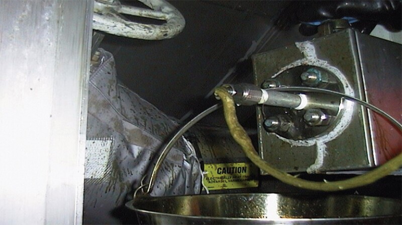
- Naphthenates, wax, and asphaltene deposits in the process vessel can also impact the functionality of the level instrumentation. An example of solid fouling due to naphthenate formation in level switch nozzle due to buildup of solids in the interface is shown in Fig 1.
Note: Addressing correct flow assurance issues should be considered during the design phase of separators, selection of suitable level instrumentation, and whenever there are level-measurement anomalies.
Location
Many factors can influence the density of the liquid within the vicinity of the level transmitter nozzles. Local variation in both pressure and temperature will have an impact on the fluid equilibrium and, hence, affect the stability of the level reading, as well as the system as a whole.
a. Downcomers
Localized changes in liquid density as well as changes in emulsion are observed in separators, where the discharge point of the mist eliminator’s downcomer/drain pipe is located adjacent to the level transmitter nozzle. The liquid caught by the mist eliminator mingles with the bulk fluid causing localized changes in density. Density fluctuations are more common in lower-density fluids. This can cause continuous fluctuation in the oil or condensate level measurement with the subsequent impact in control of the vessel operation and in downstream units.
Note: Level transmitter nozzles should not be positioned close to the downcomer discharge point, due to the risk of causing intermittent density variances, which will impact the level measurement.
b. Nozzles
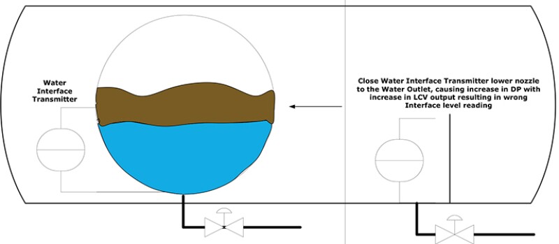
The example shown in Fig. 2 is a common level instrument piping configuration, but one that can cause issues. When issues occurred in the field, a review of the level transmitter data led to the conclusion that the interface level was being lost due to poor separation. However, the fact was that as more water was separated, the water outlet level control valve was opening up gradually, causing a Venturi effect within the proximity of the level transmitter’s lower nozzle, which is located less than 0.5 m (20 in.) from the water outlet nozzle. This caused an internal pressure drop resulting in lower interface level reading in the transmitter than was in the vessel.
Similar observations have been reported in scrubbers where the liquid outlet nozzle position is within the proximity of the lower nozzle of the liquid level transmitter.
General positioning of nozzles can also impact correct functionality, i.e., it’s harder to block off or plug a nozzle that’s on the shell of a vertical separator than it is a nozzle that is on the lower head of that separator. Similar concepts apply to horizontal vessels, where the lower the nozzle, the closer it is to any solids that settle out, making it more likely to get blocked. These aspects should be taken into consideration during the design phase of vessels.
Note: Level transmitter nozzles should not be positioned close to either inlet nozzles, liquid, or gas outlet nozzles, due to the risk of internal pressure drops, which will impact level measurement.
c. Internals
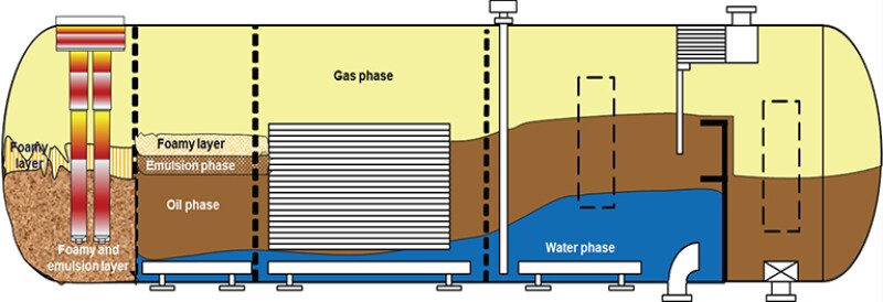
Different vessel internals can impact the separation of fluid in different ways as shown in Fig. 3, including the potential development of level gradient due to flooding of baffle plates, causing pressure drop. Such phenomenon has been observed on several occasions during troubleshooting and process diagnostic studies.
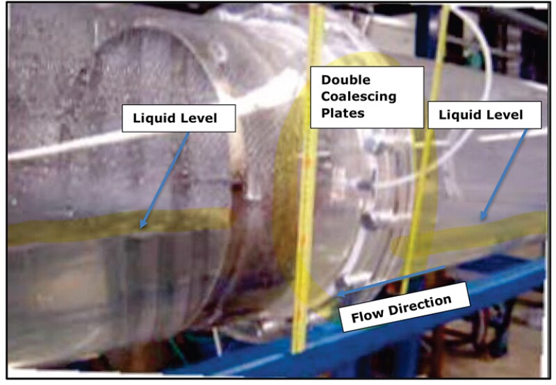
An image of level gradient in a pilot test vessel is also illustrated in Fig. 4.
Multilayer baffle plates, which are typically installed in vessels at the front end of the separator, can easily be flooded due to flow distribution issues with the inlet section. The flooding then causes a pressure drop across the vessel and consequently a fluid level gradient develops. This results in a lower liquid level in the front end of the vessel, as shown in Fig. 3. However, when the liquid level is being controlled by a level instrument at the back end of the vessel, a divergence in the measurement being taken occurs. The level gradient also causes poor separation conditions in the process vessel because at least 50% of the liquid volume is lost due to the level gradient. Also, it is conceivable that the associated high-velocity zones caused by the pressure drops create circulation zones which result in lost volume for separation.
Similar conditions can manifest in floating production units such as FPSOs where several multiperforated pads are used in a process vessel to stabilize the fluid movement within the vessels.
In addition, severe gas carry-under in horizontal vessels, under certain conditions, can create a level gradient with a higher liquid level at the front end due to lower gas dispersion. This will also have an adverse effect on the level control located at the back end of the vessel, causing measurement divergence and consequent suboptimal vessel performance.
Note: Gradient liquid levels in process vessels in different forms are a reality and attempts to minimize the occurrence should be taken, as they result in reduced separation efficiency. Improved vessel internals and a reduction in unnecessary baffle plates and/or perforating plates, coupled with good operating practices and awareness, should be employed to avoid level gradient issues within the vessel.
Conclusions
In this article several important factors impacting liquid level measurements in separators have been discussed. Erroneous or misinterpreted level readings can lead to poor vessel operation. Some recommendations have been made to help avoid the issues. Though this is by no means an exhaustive list, it helps to develop an understanding of some of the potential issues, thereby helping operations team appreciate potential measurement and operating problems.
A best practice approach, based on lessons learned, should be established if possible. However, there is no specific industry standard that can be applied in this area. To minimize the risk associated with measurement deviations and control anomalies, the following points should be considered in future design and operating practices.
Design
- More emphasis should be put on level instrumentation design, selection, and requirements during the early phase of projects, after understanding all aspects of flow assurance issues and potential limitations.
- Understand how the fluids separate within the vessel and how internals can affect liquid level. Then carefully consider the location and placement of instrument nozzles
- Include permanent flushing facilities for instrumentation tubes and nozzles as part of the vessel’s design, to allow for regular flushing of solid accumulation and condensation.
- Suitable protection for instrument nozzles from solid accumulation should be considered.
- Consider the selection and use of reliable heat tracing and/or insulation lagging material on instrumentation lines, with regular maintenance inspections.
- Consider utilizing redundant level instruments, with an additional level-monitoring device in the front end of the separator used as reference point with at least two different measurement principles.
- Where there are perforated pads, coalescing pads, and baffle plates as part of vessel configuration, level nozzles between the different regions within the vessel should be included in the design, to allow for monitoring of the differential pressure (DP) across those areas of the vessel. This can be a useful tool/indicator for monitoring potential anomalies, of foam buildup and liquid flooding of plates. It is common to have DP nozzles utilized between coalescing pads and near vessel gas outlet in vertical vessels and scrubbers to monitor potential flooding and carry-over. Similar principle should be considered for horizontal separators.
- For new horizontal separator designs, consider installing level tapping points (tricox) for use as reference points during operation and to check the accuracy of level settings.
Operations
- Regularly calibrate instrumentation with updated density values.
- Consider digital correction to level instrumentation for density deviations.
- Operate all level instrumentation with true elevation values rather than % level setting for clarity and to avoid confusion or misinterpretations.
Training
- Best practice design concepts and practices should be developed by the industry to avoid past mistakes.
- Conduct training to provide operators with a better understanding of the vessel internal configuration and instrumentation and how process conditions can affect separator performance.
Acknowledgment
I would like to thank Christopher Kalli (adjunct professor at Western Australian University, Perth Australia, and a Chevron/BP retiree); Lawrence Coughlan (consultant at Lol Co Ltd. Aberdeen, and a Shell retiree), and Paul Georgie (consultant at Geo Geo, Glasgow, UK) for peer review and critique of the paper. I would also like to thank the SPE Separations Technology Technical Section committee members for facilitating the publication of this paper. Special thanks to the members who reviewed the paper before the final issue.

Wally Georgie has over 4 decades of experience in the oil and gas industry, namely in oil and gas operation, processing, separation, fluid handling and system integrity, hands-on in operation troubleshooting, debottlenecking, oil/water separation, process verification, technology evaluation, corrosion control, system monitoring, water injection and enhanced oil recovery processing, and all other fluid- and gas-handling issues including handling sand and solid production in process systems, production chemistry, flow assurance, and integrity management.
He worked initially in the service sector in the US, UK, different parts of Europe, and Middle East between 1979 and 1987. This was followed by a career with Statoil (Equinor) in Norway from 1987 to 1999, focusing mainly on daily operation, new field project developments and production systems related to oil and water separation issues, gas treatment sweetening and dehydration systems, produced water management, and handling solid-production issues. He has been working as an independent consultant globally since March 1999 in similar areas of oil gas production. In addition, Georgie has also been working as an expert witness in legal oil and gas cases in the UK and Australia. He served as SPE Distinguished Lecturer in 2016–2017.
He holds an M.Sc. in polymer technology from Loughborough University England, an M.Sc. in safety engineering from Aberdeen University, Scotland, and a PhD in chemical technology from Strathclyde University, Glasgow, Scotland. He can be reached at wgeorgie@maxoilconsultancy.com.
You can find the rest of the Savvy Separator Series here.
Georgie presented a webinar on 9 June, “Separation Design and Operation Factors and Their Impact on Produced Water System Performance in Onshore and Offshore Facilities.” It is available on demand here (free to SPE members).