
This is the fifth in a series of six articles on SPE’s Grand Challenges in Energy, formulated as the output of a 2023 workshop held by the SPE Research and Development Technical Section in Austin, Texas.
Described in a JPT article last year, each of the challenges are discussed separately in this series: geothermal energy; net-zero operations; improving recovery from tight/shale resources; digital transformation; carbon capture, utilization, and storage; and education and advocacy.
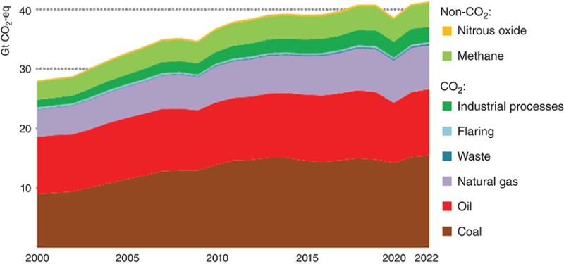
Net global anthropogenic greenhouse gases (GHG), mainly CO2 and CH4 emissions, reached nearly 60 Gt CO2-eq in 2019, with energy-related emissions contributing the largest amount at nearly 40 Gt (IPCC 2022). The fugitive emissions from coal, oil, and gas industries are about 5.8%. Fig. 1 shows the global emissions from energy-related sectors; the use of coal, oil, and natural gas contributes the major share to GHG emissions.
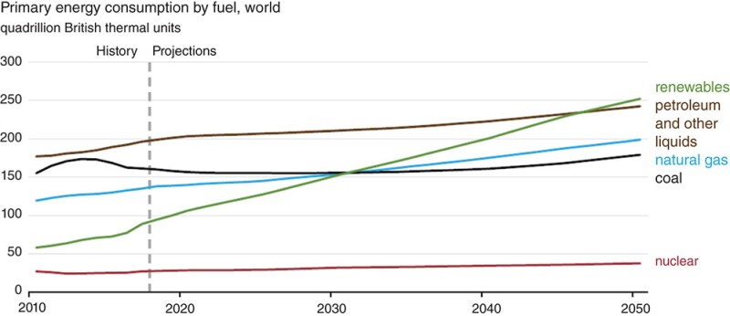
In the past 15 years, electricity production from renewable sources (solar, wind, and hydroelectric) has increased significantly. However, renewable energy accounts for only about 15% of the primary energy generation now. Almost 80% of the primary energy comes from fossil fuels: coal, oil, and natural gas, and about 5% comes from nuclear fission.
In the next 30 years, the US Energy Information Administration (EIA) projects that renewable energy will grow from 15% to about 27.6% (Fig. 2) but cannot meet human consumption by itself. Fossil fuels would still contribute about 68.5%.
How do we use fossil fuels and at the same time reduce CO2 emissions?
Fossil fuels can be used only if the associated CO2 can be captured and stored or reused. Hydrogen has been envisioned as the clean fuel for the future, but all of the needed hydrogen cannot come from electrolysis (for lack of renewable energy capacity); most will come from fossil fuels which, again, have to be supplemented with carbon capture in the net-zero economy.
CCUS has three components: carbon capture, transportation, and storage/utilization. The scale of needed CCUS dictates that the three components need to be developed simultaneously for successful deployment of this technology. For example, a power plant cannot install a carbon capture unit until transportation and storage/utilization are in operation.
CO2 Capture
Carbon capture processes separate CO2 from gaseous streams emitted from industrial sources (point sources), e.g., power plants, steel plants, and steam methane reformers (SMR). The concentration of CO2 is about 4 to 12% in power plants, 20% in steel plants, and 15 to 45% in SMR.
There are also emerging capture techniques to separate CO2 from air (with a concentration of 0.042%), called direct air capture (DAC). As the CO2 concentration decreases, it takes more energy and cost (per CO2 amount) to separate.
There are two key categories of carbon capture technology for power plants: post-combustion and pre-combustion. Post-combustion technologies include absorption, adsorption, and membrane separation; these techniques apply to other point sources also. Pre-combustion technologies can be IGCC (integrated gasification combined cycle) or oxy-combustion. In IGCC, the fuel is first gasified with steam at a high pressure to produce a synthesis gas which can be used in electricity generation, or the synthesis gas is used in a water-shift reaction to produce mostly CO2 and hydrogen. In oxy-combustion, air is separated into oxygen and nitrogen and the coal or natural gas are combusted with only oxygen. Then the gaseous product is mostly CO2, which can be sent for storage after impurity separation.
The first technique addressed in this discussion is absorption technology to separate CO2 from other gases such as nitrogen, hydrogen, or hydrocarbon gases. It is well developed where a solvent (typically an amine-water solution) absorbs CO2 from gas mixtures, and the CO2-loaded amine solution is passed through a stripper where heat is applied (mostly by steam) to remove the CO2 from the solvent, which is reused (Rochelle 2009). This technique is almost 100 years old and was developed initially for separating CO2 from natural gas; existing plants can be retrofitted with this capture technology.
The main downside of this technology is the energy needed in the stripper to remove CO2 (about 8,776 kJ/kg of CO2 for monoethanolamine [MEA]). It consumes about 30% of the energy generated and reduces the efficiency of the power generation. Many commercial solvents have been developed and are being used, such as MEA, piperazine, KS-1 (Mitsubishi), Cansolv (Shell), and mixtures of dimethyl ether and polyethylene glycol (a physical absorbent). The levelized cost is about $55 to $80/tonne of CO2 captured. New techniques are being developed using electrochemical methods to separate CO2 from flue gases instead of heat (Rahimi et al. 2022).
The second technique is adsorption where solid adsorbents are used to adsorb CO2 from gaseous mixtures. Again, heat or vacuum is used to desorb the CO2 from the solid adsorbents. The adsorbents are typically activated carbon, zeolites, or amines on mesoporous support or metal-organic-framework (MOF) materials (McDonald et al. 2016). MOF are nanoporous materials composed of metal nodes (ions or clusters) coordinated to organic linkers with specific groups to capture CO2. These frameworks have high surface area (5000–15000 m2/gm). The key issues are minizing energy for desorption and the effect of water vapor on adsorption. This is a newer technology, and the cost is slightly higher than that of amine absorption.
The third technique is membrane separation where the gas mixture/flue gas is injected into membrane separator and two gas streams come out: a gas richer in CO2 and a gas leaner in CO2. More than one stage is needed to achieve the needed purity of CO2. CO2 dissolves in the membrane and diffuses to the low-pressure side. Typically as the flux increases, the selectivity of membranes decreases. New materials are being developed to increase selectivity while maintaining flux. The key challenges are still low flux and fouling of membranes.
DAC processes involve absorption or adsorption. CO2 from air is absorbed into an alkali solution (e.g., KOH) to form K2CO3 which is further reacted with CaO to form CaCO3. The CaCO3 is heated at a high temperature (550 to 1100°C), called calcination, to release CO2 (to be stored underground) and recycle CaO.
This is an energy-intensive process, and the cost is estimated to be about $300 per ton of CO2 removed. Solid adsorbents are also being developed for this process to replace the absorption, but the cost is about $300 to $700 per ton of CO2 removed.
DAC is one of the technologies being researched for CO2 removal which includes ocean-based CO2 removal, enhanced mineralization, biomass carbon removal, and reforestation. For broad commercial deployment, energy use and costs for CO2 capture need to be reduced.
CO2 Transport
For large-scale CCUS, CO2 must be transported in pipes. The same type of steel as used in natural gas pipelines can be used, if the CO2 is dry (no free water) and has a water vapor content of less than 30 lb/MMscf. This is important because the presence of free water in CO2 can lead to the formation of carbonic acid, which can cause significant corrosion in steel pipelines.
CO2 pipelines should be operated above 1,300 psi because at this pressure, the density of CO2 is liquid-like (about 500 to 700 kg/m3), and the viscosity is gas-like (below 0.1 cP). Therefore, pumps can be used instead of compressors to save energy.
These pipelines are regulated in the US by the Pipeline and Hazardous Materials Safety Administration under CFR Part 195. Such CO2 pipelines exist in some parts of the US to serve CO2-EOR (enhanced oil recovery) projects. Similar regional networks of pipelines (CO2 hubs) need to be developed to connect point-source industries and storage sites.
CO2 Utilization
CO2 can be utilized to make chemicals, but this must be done at scale (Gt/year) to make an impact on GHG emissions. Current use of CO2 is about 100 Mt per year, and most of it goes into the oil and gas industry for EOR. The other uses are in production of urea, sodium carbonate, food, and the beverage industry. Other chemicals can be made from CO2, for example, formic acid. The chemical that is used the most globally is sulfuric acid and its production is about 200 Mt/year (Bhown & Freeman 2011). It is unlikely that many Gt/year CO2 can be used to produce useful chemicals. Thus, it is necessary to develop CO2 storage at scale.
CO2 Storage
Captured CO2 can be stored in underground formations (sedimentary rocks), requiring pressurization and transportation to geological storage sites such as aquifers, depleted hydrocarbon reservoirs, and coal seams. The technology for injecting high-pressure (supercritical) CO2 into underground formations and sealing the wells with cement is well developed from CO2-EOR operations conducted over the past 50 years. Every storage reservoir must have a seal (a caprock) where the injected CO2 cannot pass through, and the capillary pressure must exceed the buoyancy force. This limits the height of the connected CO2 column. The total global capacity has been estimated to be 8,000 to 55,000 Gt of CO2 (IEA 2021).
Typically, CO2 is injected into aquifers ranging from 1 to 2 km deep for storage without production of any brine, which increases the pressure in the aquifer and must be kept below fault-activation pressure or fracture pressure. In aquifers CO2 is trapped by four mechanisms: structural trapping (seal above the storage reservoir), capillary trapping (residual CO2 saturation), solution trapping (dissolution of CO2 in water), and mineral trapping (CO2 reacts with minerals and brine to form carbonate minerals over a long time). CO2 storage has been tried out in many fields successfully (e.g., Sleipner in North Sea) (Singh et al. 2010).
Aquifer storage is given high priority because of the availability of the vast amount of storage space in aquifers all over the earth (IEA 2021). The key challenge for aquifer storage is the characterization of its seal and faults for storage assurance. Seismic analysis can be used to characterize the seals and major faults, but the minor faults cannot be detected. The number of wells drilled in potential aquifers is limited, so the core data is scarce. Long-term monitoring must be installed after CO2 injection. Monitoring technology includes pressure and seismic monitoring in wells, chemical monitoring in zones above the storage layer, and 4D seismic. The risk of leakage is small, but the long-term liability with carbon capture and storage (CCS) should be clearly stated during permitting.
In contrast, depleted hydrocarbon reservoirs are well characterized during the production phase and through many drilled wells. CO2 can be injected into depleted oil and gas reservoirs with or without hydrocarbon production. Production of the hydrocarbon provides the revenue that can decrease the cost of carbon storage and increase the storage volume for CO2. The original pressures of these reservoirs are well known and the CO2 can be injected from the depleted pressure to the original pressure without concern for fault activation or out-of-zone fractures.
CO2 injection has been tested in many fields for CO2 storage (e.g., Weyburn-Midale in Canada) (Wildgust et al. 2013). In the past 50 years, CO2 has been injected in many west Texas reservoirs for EOR with no cases of CO2 leak. The estimated storage capacity in hydrocarbon reservoirs varies from 900 to1,200 Gt of CO2 (Benson & Surles 2006). There are two key challenges. Many of the old hydrocarbon reservoirs are onshore and abandoned, and old wells need to be located and sealed to assure permanent storage. Also, the landowners must agree to CCS projects.
Subsurface Mineralization
There are many rocks in the subsurface rich in Ca, Mg, and Fe silicates (e.g., olivine, serpentine, wollastonite, and basalt). When these rocks are exposed to CO2 and water, hydrothermal reactions take place to produce the respective carbonates (calcite, magnesite, and siderite) (Gadikota et al. 2020). These carbonates represent the lowest energetic state of CO2 and hence the safest state for CO2 sequestration. Processes are being studied to do mineralization in-situ if the rock is porous or ex-situ if the crushed rock can be delivered to the emission site (O’Connor et al. 2005). McGrail et al. (2017) report a successful pilot test in Wallula basalt in the US state of Washington, demonstrating supercritical CO2 injection and fast mineralization in flood basalt. Carbfix is a small (12,000 ton/year) commercial project in Iceland where CO2 is dissolved in brine and is injected into a volcanic formation to mineralize CO2 (Snæbjörnsdóttir et al. 2020).
Looking Forward
The current global CCUS capacity is 41 million metric ton/year which is 0.1% of global CO2 emissions. To make an impact, this industry has to grow several hundred times within a decade; that is an opportunity and a challenge. The technology is there, but the infrastructure, economic incentives, regulations, and public awareness are not. Today, regional supply chains linking CO2 capture sites, pipelines, and storage reservoirs do not exist except for a few locations. CCUS hubs must be built to take advantage of economies of scale by combining resources and sharing CO2 transportation and storage among several emitters, thereby distributing the risks. The US has tax incentives like 45Q for CO2 storage, and their impact on CCS is substantial (Steele et al. 2021). There should be clarity and consistency in government policies. At the end of the day, people have to pay for the cost of CCS (a waste disposal process) in one way or another. Public awareness of the enormity of the issue and the urgency of implementing solutions is imperative before CCUS can be implemented at scale.
For Further Reading
Summary for Policymakers. Intergovernmental Panel on Climate Change.
https://www.ipcc.ch/report/ar6/wg2/downloads/report/IPCC_AR6_WGII_SummaryForPolicymakers.pdf
Carbon Dioxide Capture and Storage: An Overview With Emphasis on Capture and Storage in Deep Geological Formations by S.M. Benson, Stanford University; and T. Surles, University of Hawai’i at Manoa.
Analysis and Status of Post-Combustion Carbon Dioxide Capture Technologies by A.S. Bhown, Electric Power Research Institute.
Functionalized Polyaniline-Based Composite Membranes With Vastly Improved Performance for Separation of Carbon Dioxide From Methane by N. Blinova and F. Svec, Lawrence Berkeley National Laboratory.
Elucidating the Difference in the Carbon Mineralization Behaviors of Calcium- and Magnesium-Bearing Alumino-Silicates and Magnesium Silicates for CO2 Storage by G. Gadikota, Cornell University; G. Matter, University of Southampton; and P. Keleman, Lamont-Doherty Earth Observatory of Columbia University, et. al.
The World Has Vast Capacity To Store CO2: Net-Zero Means We’ll Need It, International Energy Agency.
Cooperative Insertion of CO2 in Diamine-Appended Metal Organic Frameworks by T. McDonald, J. Mason, and X. Kong, University of California-Berkeley, et. al.
Wallula Basalt Pilot Demonstration Project: Post-Injection Results and Conclusions by B.P. McGrail, H.T. Schaef, and F.A. Spane, Pacific Northwest National Laboratory, et. al.
Aqueous Mineral Carbonation by W.K. O’Connor, D.C. Dahlin, and G.E. Rush, Office of Process Development, National Energy Technology Laboratory, et. al.
Electrochemical Carbon Capture Processes for Mitigation of CO2 Emissions by M. Rahimi, University of Houston; and A. Khurram and T.A. Hatton, Massachusetts Institute of Technology, et. al.
Amine Scrubbing for CO2 Capture by G.T. Rochelle, The University of Texas at Austin
SPE 134891 Reservoir Modeling of CO2 Plume Behavior Calibrated Against Monitoring Data From Sleipner, Norway by V.P. Singh and H. Hansen, Statoil ASA; and A. Cavanagh, Permedia Research Group Inc., et. al.
Carbon Dioxide Storage Through Mineral Carbonation by S. Snæbjörnsdóttir, B. Sigfússon, C. Marieni, et al., Lamont-Doherty Earth Observatory, et al.
Comparative Analysis of Carbon Capture and Storage Finance Gaps and the Social Cost of Carbon by A. Steele, T. Warner, and D. Vikara, National Energy Technology Laboratory, et. al.
International Energy Outlook 2019, US Energy Information Administration.
Introduction to a Decade of the Research by the IEAGHG Weyburn-Midale CO2 Monitoring and Storage Project by N. Wildgust, University of North Dakota; C. Gilboy, Saskatchewan Industry and Resources; and P. Tontiwachwuthikul, Clean Energy Technologies Research Institute.

Kishore K. Mohanty is the W.A. (Monty) Moncrief Centennial Chair Professor in Petroleum Engineering in the Hildebrand Department of Petroleum and Geosystems Engineering at The University of Texas at Austin. His research interests are in carbon capture and storage, enhanced oil recovery, and nanotechnology. He has won several SPE awards including the John Franklin Carll Award for Distinguished Professionals (2022), SPE Distinguished Achievement Award for Petroleum Engineering Faculty (2016), and AIME/SPE Anthony F. Lucas Gold Medal for Technical Leadership (2013). He holds a BS degree from IIT-Kanpur and a PhD from the University of Minnesota, both in chemical engineering.